Wellhead drive brake system

a brake system and wellhead technology, applied in the direction of positive displacement liquid engines, well accessories, liquid fuel engines, etc., can solve the problems of rod string and pump being lost down the hole, rod string and pump being lost, and serious problems occured

Inactive Publication Date: 2007-12-20
GRENCO ENERGY SERVICES
View PDF9 Cites 7 Cited by
  • Summary
  • Abstract
  • Description
  • Claims
  • Application Information

AI Technical Summary

Problems solved by technology

However, because of the typical depth of an oil well, the torque applied at the top of the rod string, and the resistance of the pump at the bottom, can cause the rod string to wind up like a spring, thus storing the torque energy.
Without any control on the rate of backspin of the rod string, serious problems have occurred, for example: the motor, connected to the rod string through a reducer and a sheave and pulley arrangement, may reach reverse speeds exceeding safe limits.
These speeds t...

Method used


Image

  • Wellhead drive brake system
  • Wellhead drive brake system
  • Wellhead drive brake system

Examples


Embodiment Construction

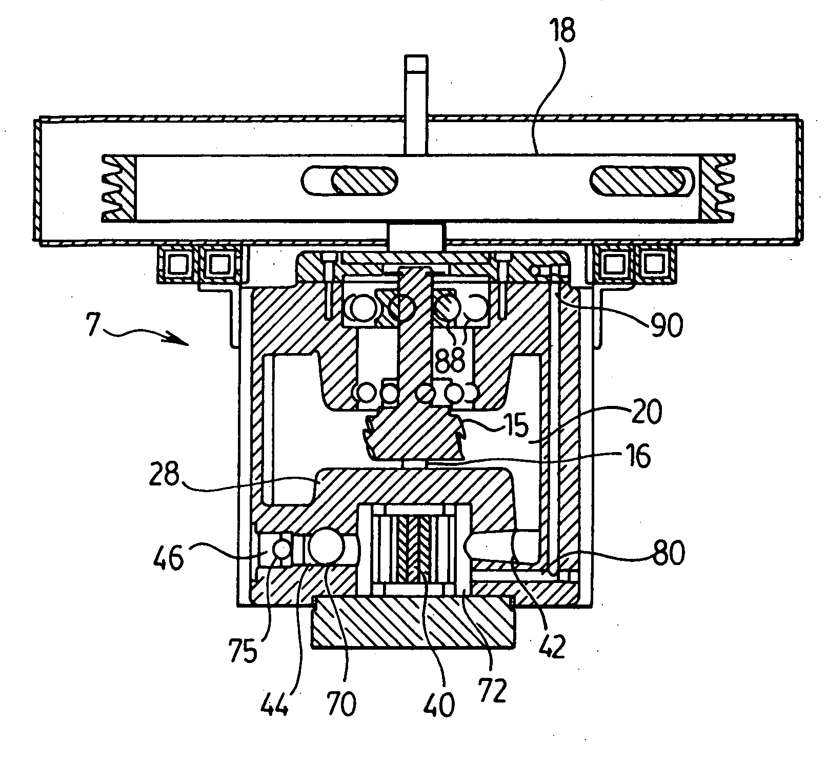
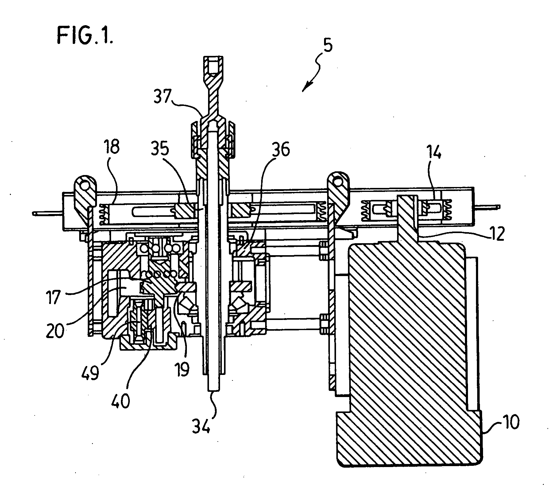
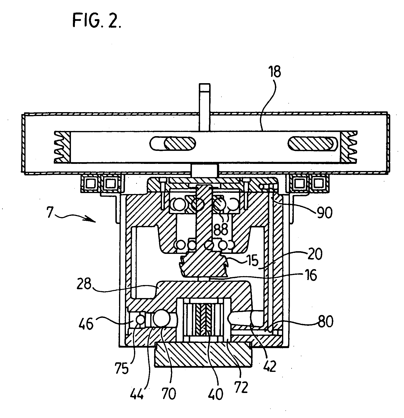
[0014] In one aspect, the present invention provides a braking mechanism which, without using a slip clutch, slows the backspin of a rod string by using the rotational energy of the rod string to turn a fluid pump to pump fluid through a constriction orifice in a closed fluid circuit. As compared to the prior art described in the background, the present invention reduces the space required for the braking mechanism and moreover reduces the number of moving parts within the braking mechanism which in turn may reduce the likelihood that the braking mechanism will require maintenance or fail, as well as reduce the manufacturing cost.

[0015] In another aspect, the present invention provides a wellhead drive system which employs the inventive braking mechanism in a wellhead drive system for driving a pump, for example a progressive cavity pump.

[0016] A preferred embodiment of the braking mechanism of the present invention is accomplished by providing for use with a pumping system in whi...


PUM


Abstract

The present invention provides in one aspect a braking mechanism for slowing the release of torsional potential energy in a rod string of a wellhead drive system on the shutdown or power failure thereof. The braking mechanism, without using a slip clutch, slows the backspin of the rod string by using the rotational energy of the rod string to turn a fluid pump to pump fluid through a constriction orifice in a closed fluid circuit. The present invention reduces the space required for the braking mechanism and moreover reduces the number of moving parts within the braking mechanism which may reduce the likelihood that the braking mechanism will require maintenance or fail, as well as reduce the manufacturing cost. In another aspect, the present invention provides a wellhead drive system for driving a rotary downhole pump which includes the inventive braking mechanism described above.

Description

FIELD OF THE INVENTION [0001] This invention relates to oil production equipment. In particular, the invention relates to an improved braking mechanism for a wellhead drive system and a wellhead drive system including said improved braking mechanism. BACKGROUND OF THE INVENTION [0002] In the past, many conventional oil wells were serviced by a downhole pump at or close to the bottom of the well, the pump being of a conventional reciprocating kind actuated by a rod string, in turn reciprocated vertically by a pump jack. [0003] Many of these older reciprocating pumps have been replaced by rotary-drive progressive cavity pumps. Such rotary pumps are particularly suited for the production of crude oil laden with sand and water. [0004] However, because of the typical depth of an oil well, the torque applied at the top of the rod string, and the resistance of the pump at the bottom, can cause the rod string to wind up like a spring, thus storing the torque energy. Whenever there is a powe...

Claims


Application Information

Patent Timeline
IPC IPC(8): F04B49/00
CPCF04C2/18E21B43/126
Inventor GRENKE, EDWARD
Owner GRENCO ENERGY SERVICES
Why Eureka
Try Eureka