Method for draining an oil well and system for implementing said method

A technology for oil wells and excitation systems, applied in the field of electrical systems, can solve problems such as system failure, high cost, and impossibility to ensure safety, and achieve the effect of avoiding costs and improving reliability

Inactive Publication Date: 2018-04-13
MOTEURS LEROY SOMER
View PDF15 Cites 0 Cited by
  • Summary
  • Abstract
  • Description
  • Claims
  • Application Information

AI Technical Summary

Problems solved by technology

In case of technical failure of the motor, the system does not work
Additionally, the power contactors, associated safety equipment and resistor blocks make this system relatively complex and relatively expensive
[0012] It is therefore not possible with most known systems to guarantee that the maximum temperature reached during the process of draining the well does not reach the explosive threshold of the immediate environment above the well, or to ensure a fully satisfactory safety in overspeed conditions

Method used


Image

  • Method for draining an oil well and system for implementing said method
  • Method for draining an oil well and system for implementing said method
  • Method for draining an oil well and system for implementing said method

Examples


Embodiment Construction

[0043] figure 1 An oil well W is schematically shown, in the bottom of which is submerged a pump P, preferably a progressive cavity pump, driven from the surface by a motor M via a drive rod T and a gearbox 10 .

[0044] According to the invention, a system 20 for decelerating the drive rod T is provided to avoid a runaway installation in case of changes in the operating conditions of the installation, especially when the motor M is stopped, and to ensure that the installation is performed in good safety conditions ( Especially when the maximum temperature is reached) the well W is drained.

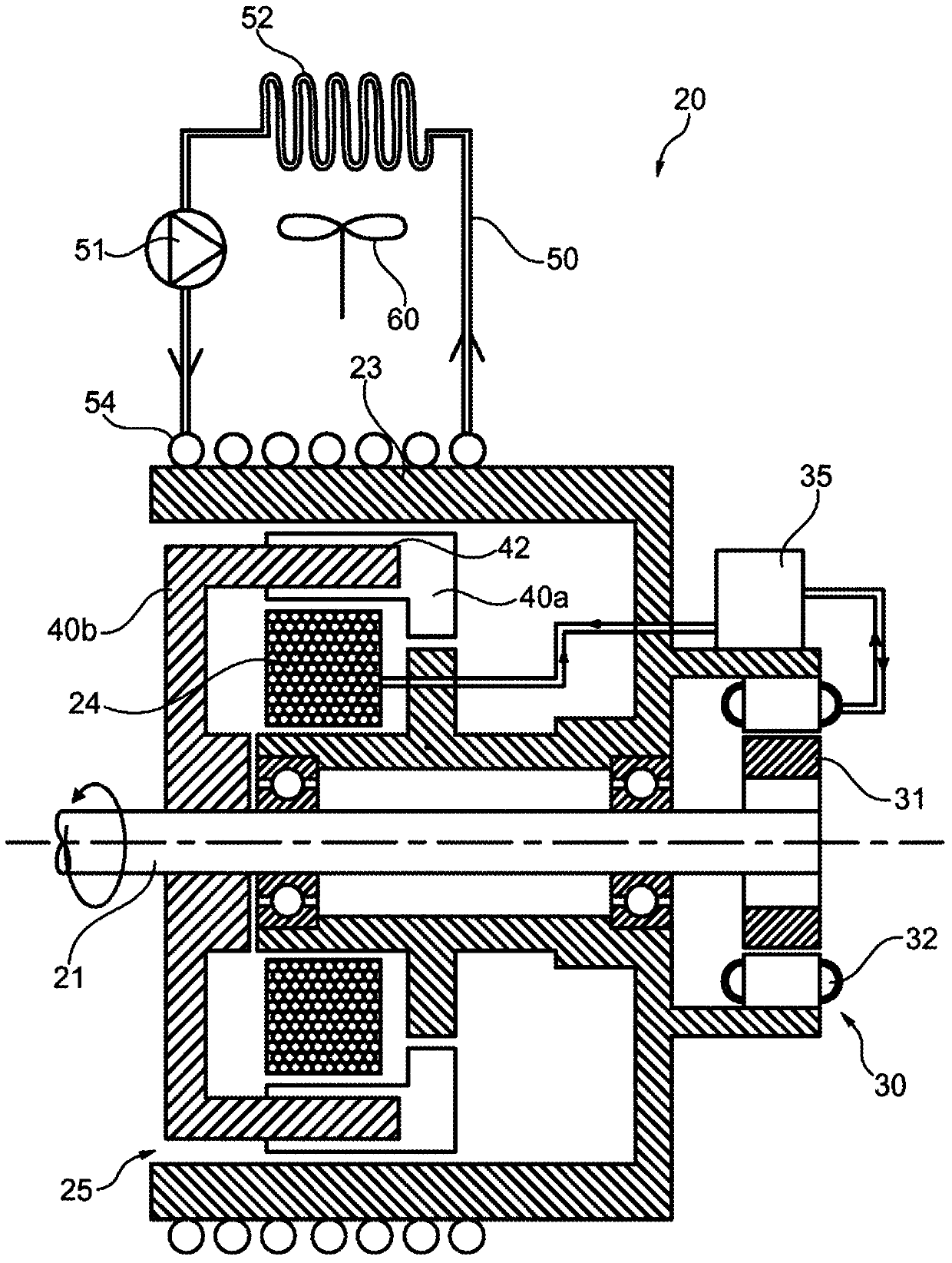
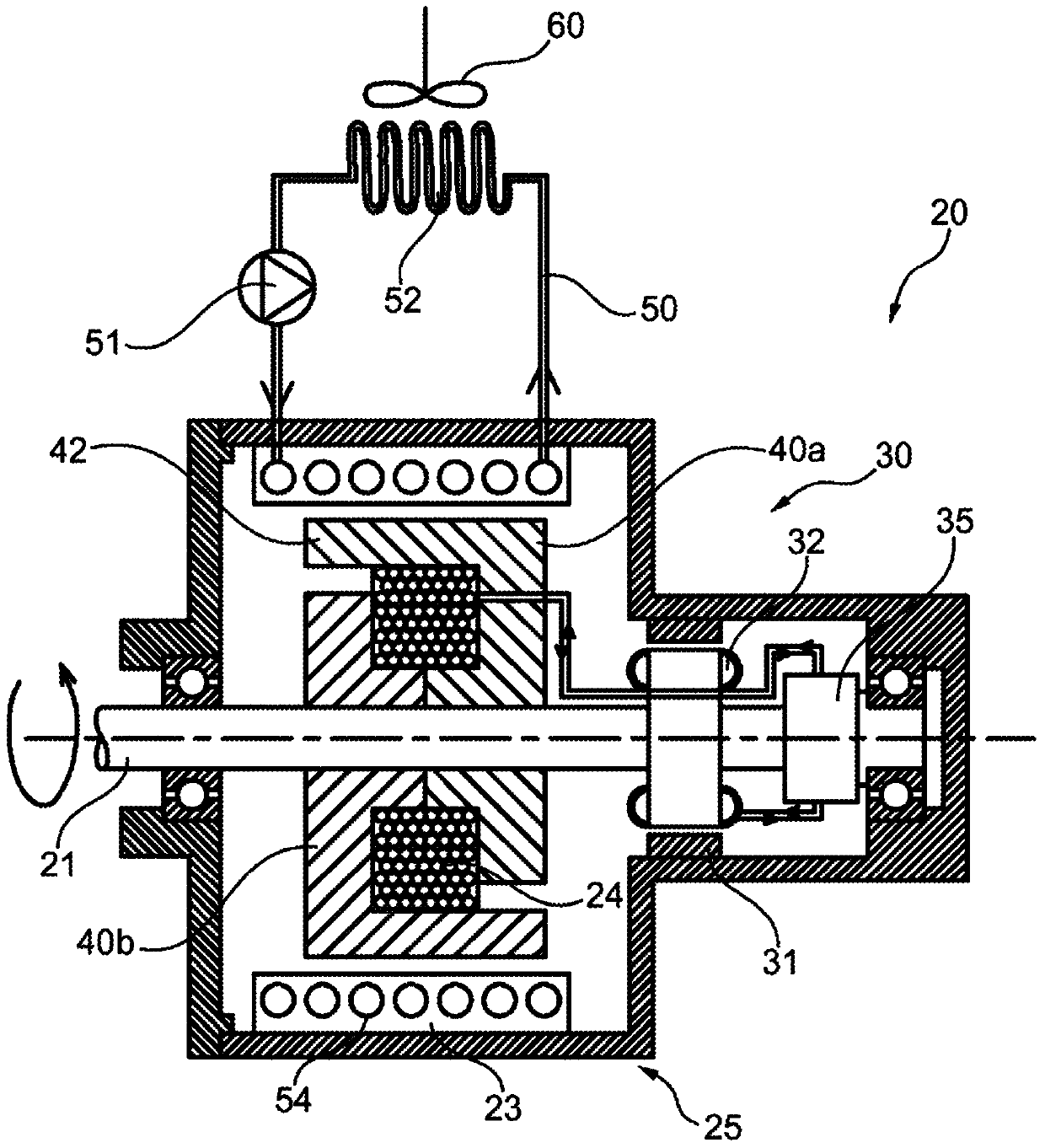
[0045] According to the invention, the reduction system 20 comprises an eddy current reducer 25 .

[0046] deceleration system

[0047] The reduction system 20 can have different configurations, in Figure 2 to Figure 5 An example of a reduction system has been given schematically in .

[0048] In these figures, the drive shaft 21 of the reduction system 20 is very schematically repre...


PUM


Abstract

The invention relates to a method for controlling the emptying of (P) an oil well (W) comprising a submerged pump driven on the surface by a motor (W) driven by A rod (T) is connected to the pump, the method comprising the steps of: when the drive of the pump by the motor is interrupted and the pressure of the fluid column in the drive rod especially in the well and the pressure of the fluid column in the drive rod In the event of rotation in the reverse direction under the action of torsional potential energy accumulated in the drive rod, the drive rod is decelerated by applying a braking torque using a deceleration system (20) with eddy currents.

Description

technical field [0001] The present invention relates to electrical systems capable of decelerating driven devices and in particular but not limited to drive systems dealing with driven devices that have the potential to store large amounts of potential energy during their operation. Background technique [0002] The main application covered by the invention is the drive system of an oil well pump, which is a pump with a slow rotational speed, typically around 500 rpm, used in oil wells. The pump is placed at the bottom of the well, and the drive system is at the top of the well, which can be deeper than 2000 meters. [0003] Pumps are traditionally driven by an electric motor through a gearbox with pulleys and belts or with gears. [0004] In operation, devices utilizing such pumps store two forms of potential energy, namely, on the one hand, the torsional energy in the drive rod resulting from the torsion of the rod itself, and on the other hand, corresponding to the force...

Claims


Application Information

Patent Timeline
Patent Type & Authority Patents(China)
IPC IPC(8): E21B41/00E21B43/12E21B47/00H02K49/04
CPCE21B41/0021E21B43/126H02K49/043H02K7/20H02K9/06E21B47/008H02K5/203
Inventor 埃里克·考帕特菲利普·加洛德雅克·圣米歇尔
Owner MOTEURS LEROY SOMER
Why Eureka
Try Eureka