
Evacuation Status Indicator (ESI)

a technology of status indicator and evacuation process, applied in the field of evacuation status indicator, can solve the problems of wasting valuable time, putting patients, staff and rescue personnel at unnecessary risk, and not providing the most efficient method of communicating evacuation, so as to save rescue personnel valuable time and save lives

Inactive Publication Date: 2007-12-27
STEVENS SAUNDRA JANESE +1
View PDF32 Cites 3 Cited by
  • Summary
  • Abstract
  • Description
  • Claims
  • Application Information

AI Technical Summary

Benefits of technology

[0010]The Evacuation Status Indicator (ESI) is a device, which, when activated, indicates that the room to which it is attached, has been evacuated of all occupants. Use of the ESI saves lives by saving rescue personnel valuable time during an emergency evacuation. It eliminates the need to search a room that has already been evacuated. As a result, rescue personnel can proceed to other rooms or areas of the affected premises that have not been evacuated. The ESI is mounted on the exterior side of a room near or on the room's exit door. During an evacuation situation, when all occupants have been removed from (or have exited) the room, the ESI is activated. It then serves as an indicator to anyone searching or evacuating at a later time that the room is empty.

Problems solved by technology

Each of these communication systems has weaknesses and does not provide the most efficient method of communicating the evacuation status of the affected room.
These methods put patients, staff, and rescue personnel at unnecessary risk.
1. Require retrieval from some storage location—The current methods utilize items that are not located at the point of use. Therefore they have to be retrieved at the time of the emergency. This takes valuable time away from the evacuation process.
2. Items utilized could be misplaced—The items utilized in the current methods are not affixed to the point of use possibly resulting in being misplaced and not available at the time of the emergency.
3. Application of the method is clumsy and / or difficult—Getting the pillowcase off of the pillow is clumsy and placing a sign on a hook can be difficult in a tense situation thus again wasting valuable time.
3. These methods and devices may not hold up to either the heat from a fire (in the case of the chalk or the sign) or the traffic of the evacuation process (in the case of a pillow case on the floor). In either case, the indicator is rendered inadequate resulting in no communication to other evacuation personnel.
4. These methods and devices would be difficult to see in conditions of poor visibility (i.e. smoke or dim to no light).

Method used


Image

  • Evacuation Status Indicator (ESI)
  • Evacuation Status Indicator (ESI)
  • Evacuation Status Indicator (ESI)

Examples


Embodiment Construction

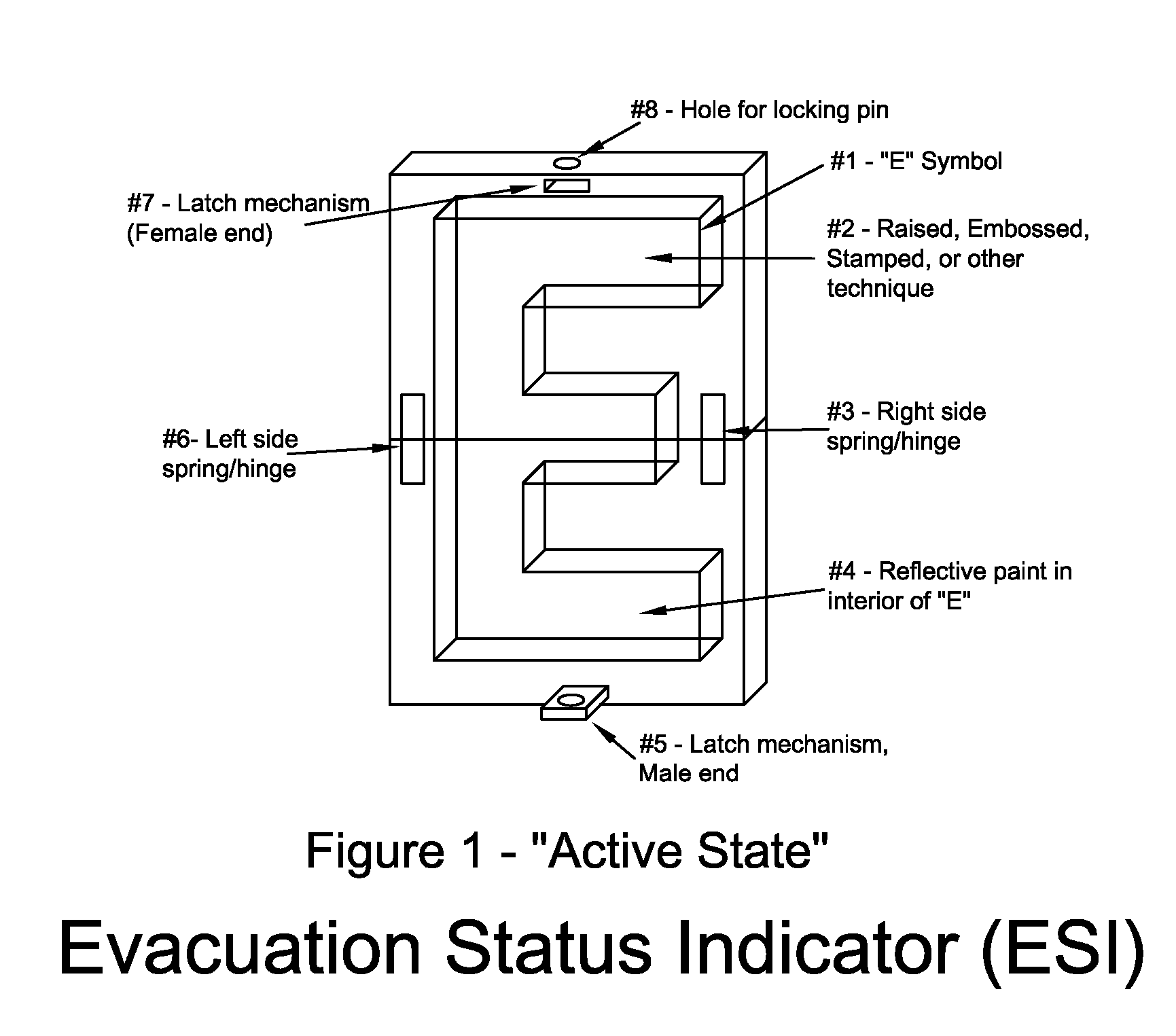
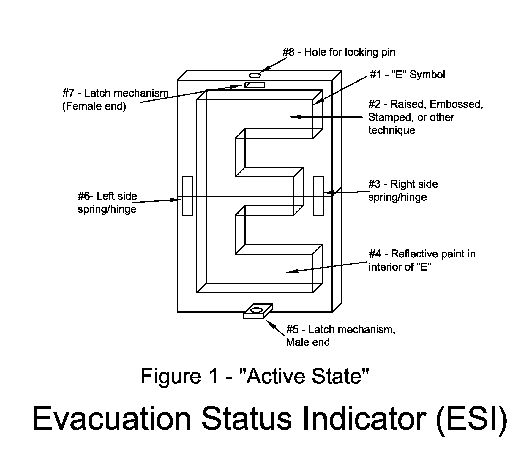
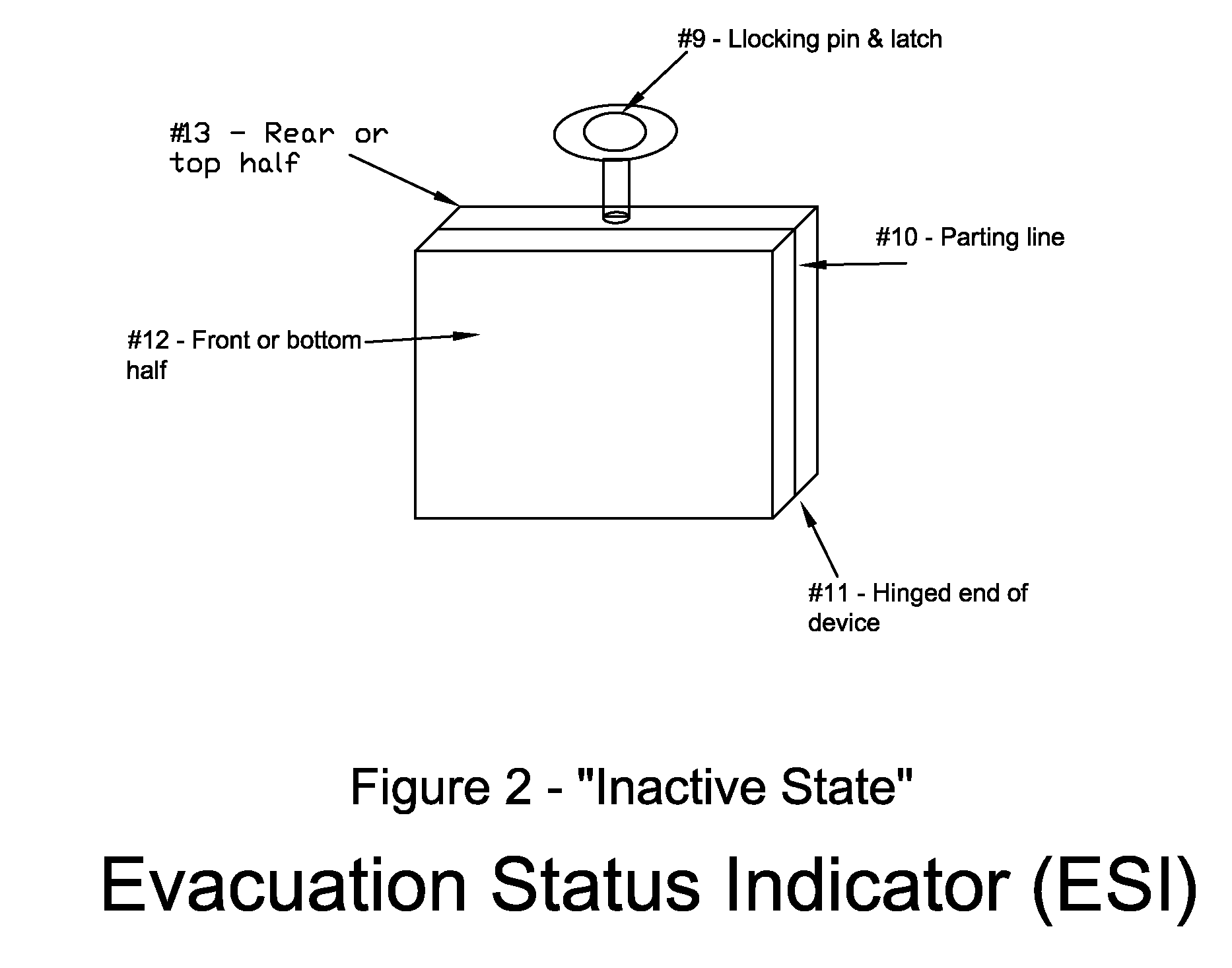
[0015]Referring to FIG. 2, the invention can be seen in the “inactive” state. The invention is shown to be a rectangular cube, however to anyone skilled in the art, this could be shaped in any number of three-dimensional forms. In the closed state, the invention is shown to have two halves with the front (or bottom) half 12 separated from the rear (or top) half 13 by parting line 10. The rear (or top) half 13 is rigidly connected to a wall (or door) while the front (or bottom) half 12 is not. The device is activated by pulling the locking pin 9 from the latch. The locking pin and latch 9 is shown as a non-descript latch mechanism. As such, the locking pin and latch 9 can be any number of latch mechanisms common to anyone skilled in the field of latches. When the locking pin 9 is pulled, the device opens along parting line 10 by rotating about the hinged end of the device 11. The device can be seen in the “activate” state in FIG. 1. The “activate” state of the device reveals the lett...


PUM


Abstract

A new device used in institutions such as, but not limited to, hospitals, nursing homes, and other patient-care facilities, and hotels and cruise ships which, when activated, provides a visual indication locally, at or near the room to which it is attached, as to whether or not a particular room has been evacuated during an emergency evacuation situation.

Description

[0001]This application claims priority of provision application No. 60 / 816,379 filed on Jun. 26, 2006.CROSS-REFERENCE TO RELATED APPLICATIONS[0002]Not ApplicableSTATEMENT REGARDING FEDERALLY SPONSORED RESEARCH OR DEVELOPMENT[0003]Not applicableREFERENCE TO SEQUENCE LISTING, A TABLE, OR A COMPUTER PROGRAM LISTING COMPACT DISC APPENDIX[0004]Not applicableBACKGROUND OF THE INVENTION[0005]Many hospitals and nursing homes are required by State, Federal, and International laws to establish and document emergency evacuation procedures. In the case of a fire emergency, these institutions are required, among other things, to document a method for evacuating all patients from their rooms to a safe area. One critical aspect of the evacuation process is effective communication among staff as to which rooms have been evacuated. State, Federal, and in some cases, International regulations leave the method of communication up to each institution's administration. As such, several techniques have b...

Claims


Application Information

Patent Timeline
Patent Type & Authority Applications(United States)
IPC IPC(8): G09F11/00
CPCG09F11/00G09F7/00
Inventor STEVENS, SAUNDRA JANESEFULLER, ROBERT GLENN
Owner STEVENS SAUNDRA JANESE
Learn More