Electrical Device Containing Insulating Gas Under Pressure and Including a Composite Insulator Provided With a Window for Observing Contacts

a technology of insulating gas and composite insulator, which is applied in the direction of air-break switch, high-tension/heavy-dress switch, contact mechanism, etc., can solve the problem of restricting the choice of materials available for performing the function

Inactive Publication Date: 2007-12-27
ALSTOM TECH LTD
View PDF5 Cites 13 Cited by
  • Summary
  • Abstract
  • Description
  • Claims
  • Application Information

AI Technical Summary

Benefits of technology

[0011] Together, the materials used, make it possible to ensure: gas-tightness, the electrical installation...

Problems solved by technology

Together, these selection criteria put a restriction on the ...

Method used


Image

  • Electrical Device Containing Insulating Gas Under Pressure and Including a Composite Insulator Provided With a Window for Observing Contacts
  • Electrical Device Containing Insulating Gas Under Pressure and Including a Composite Insulator Provided With a Window for Observing Contacts
  • Electrical Device Containing Insulating Gas Under Pressure and Including a Composite Insulator Provided With a Window for Observing Contacts

Examples


Embodiment Construction

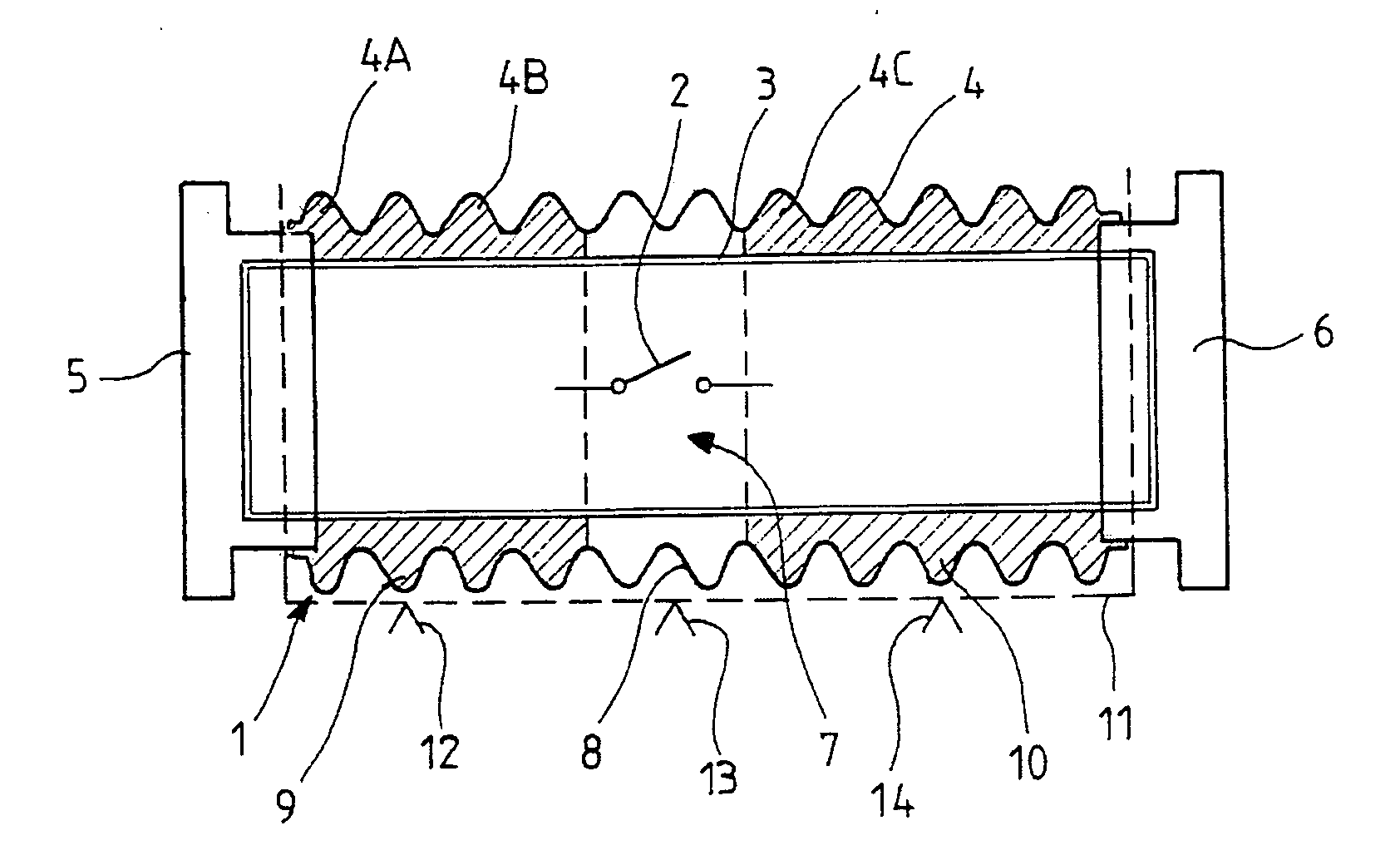
[0034] In FIG. 1, a high or medium voltage electric switch device 1 of the invention comprises switch contacts 2 capable of occupying an open position and a closed position, and disposed inside a composite insulator formed by a rigid tube 3 surrounded by an elastomer casing 4.

[0035] Inside the tube, the switch contacts 2 comprise a fixed contact assembly and a moving contact assembly. The moving contact assembly is disposed in the zone halfway along the tube as shown in FIG. 1. When the switch contacts are in the open position, it should be understood that the moving contact assembly is in a position such that it is not electrically connected to the fixed contact assembly.

[0036] As can be seen in FIG. 1, the elastomer casing has an outside surface which defines a succession of annular fins such as 4A, 4B, 4C that share a common axis and that are distributed along the tube 3 between two metal end fittings 5 and 6 of the composite insulator in which the two ends of the tube 3 are fi...


PUM


Abstract

The gas-tight, high or medium voltage electric switch device (1), containing an insulating gas under pressure, comprises switch contacts (2) capable of occupying an open position and a closed position and disposed inside a composite insulator formed by a rigid tube (3) surrounded by an elastomer casing (4) whose outside surface defines a succession of annular fins. The rigid tube and the elastomer casing are arranged so as to define an observation window (7) that is at least translucent, and through which the open or closed position of the switch contacts is visible.

Description

TECHNICAL FIELD [0001] The present invention relates to a gas-tight, high or medium voltage, electric switch device containing insulating gas under pressure, and comprising an enclosure containing switch contacts capable of occupying an open position and a closed position, together with a system for identifying the open or closed position of the switch contacts from outside the enclosure. STATE OF THE PRIOR ART [0002] Patent document DE-195 19 721 discloses a circuit breaker of the above-specified type in which the enclosure is constituted by a metal casing filled with a dielectric insulating gas such as SF6 under a pressure of a few bars, and the system for identifying the position of the switch contacts is constituted by an optical barrier located inside the spacing between the fixed contact and the moving contact, and by optical fibers which deliver an optical signal to the outside of the enclosure to indicate the position of the switch contacts. [0003] U.S. Pat. No. 4,249,050 di...

Claims


Application Information

Patent Timeline
IPC IPC(8): H01H33/53
CPCH01H33/53H01H2033/6623H01H2011/0081H01H2009/0292
Inventor LINDNER, CHRISTIANBESSEDE, JEAN-LUCKIEFFEL, YANNICK
Owner ALSTOM TECH LTD
Why Eureka
Try Eureka