Method and apparatus for controlling a haptic device

a haptic device and controller technology, applied in the field of haptic devices, can solve the problems of endpoint movement, large deleterious effect on haptic performance, and error between actual endpoints

Active Publication Date: 2007-12-27
MAKO SURGICAL CORP
View PDF46 Cites 70 Cited by
  • Summary
  • Abstract
  • Description
  • Claims
  • Application Information

AI Technical Summary

Problems solved by technology

Although this scheme permits good haptic performance of the haptic device, one drawback is that the calculated position of the endpoint, and thus the haptic surfaces, in physical space may not correspond to the actual position of the endpoint due to compliance and hysteresis in the cable transmission.
For example, when the user applies a force to the distal end of the haptic device, the cable transmission may flex, resulting in endpoint movement even if the controller maintains the actuator output position.
This movement results in an error between the actual endpoint location relative to the location of the endpoint as computed by the controller based on the actuator output position.
In addition, such haptic devices are generally designed to be compact and have minimal moving mass and inertia, so they typically will not have extra position sensors, especially on the load end of the transmission, where the sensors will have a larger deleterious effect on the haptic performance.
One drawback of stiff transmissions, however, is that they may not be backdriveable and/or suitable for use in a haptic device.
Although conventional cable drive haptic devices are backdriveable, they present the endpoint positioning accuracy problem described above.
Relocating the sensors to the load end of the cable tran...

Method used


Image

  • Method and apparatus for controlling a haptic device
  • Method and apparatus for controlling a haptic device
  • Method and apparatus for controlling a haptic device

Examples


Embodiment Construction

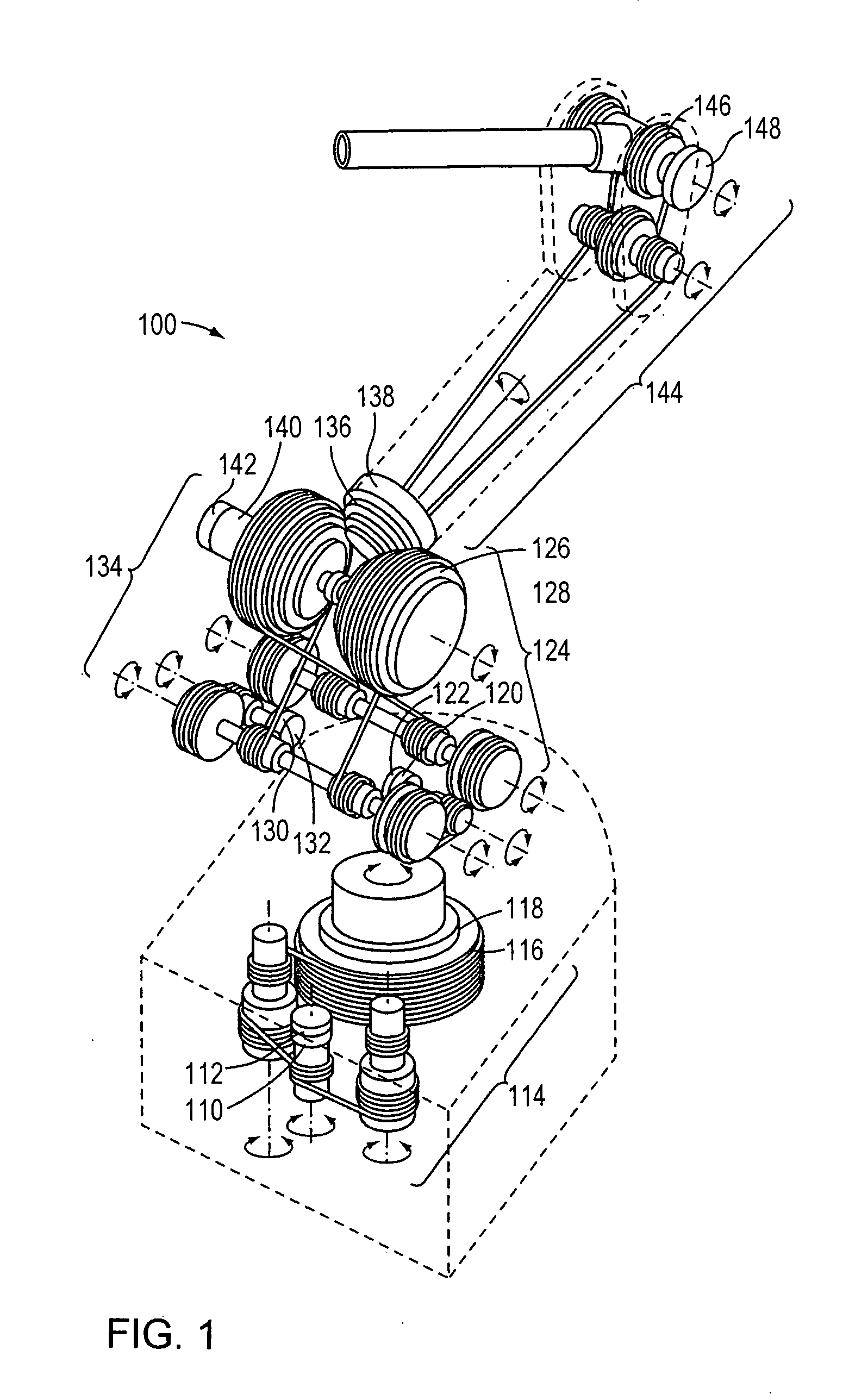
[0027] Referring to FIG. 1, an embodiment of a portion of a cable drive haptic device of the invention is shown. The cable drive haptic device comprises an arm 100 that includes cable drive transmissions 114, 124, 134, 144, which are all backdriveable. For each transmission 114, 124, 134, 144, rotary actuators 110, 120, 130, 140 are positioned at one end of the respective transmission (i.e., the proximal or drive end) and joint links 116, 126, 136, 146 are positioned on the other end (i.e., the distal or load end) of the respective transmission. The arm 100 is equipped with four drive end sensors 112, 122, 132, 142 installed on rotary actuators 110, 120, 130, 140 as well as four load end sensors 118, 128, 138, 148 installed on joint links 116, 126, 136, 146.

[0028] In this embodiment, the cable drive transmissions provide a gear reduction so that smaller actuators can be used without introducing backlash, friction, or other non-linear effects that make control difficult. However, be...


PUM


Abstract

A method and apparatus for controlling a haptic device. In one embodiment, the haptic device includes an actuator; an actuator sensor, producing an actuator signal indicative of the actuator velocity; a load; a load output sensor producing a load output signal indicative of the load position; and a controller in electrical communication with the load output sensor, actuator sensor and actuator. The controller controls the actuator in response to the actuator signal and the load output signal to provide a haptic response to a user. In one embodiment, the method for controlling an actuator of a haptic device includes the steps of producing an actuator signal indicative of the velocity of an actuator; producing a position signal indicative of the position of a load; and controlling the actuator in response to the actuator signal and the load output position signal to produce a haptic response to a user.

Description

RELATED APPLICATIONS [0001] This application claims priority to U.S. Provisional Patent Application 60 / 801,850 filed on May 19, 2006, the disclosure of which is herein incorporated by reference in its entirety.FIELD OF THE INVENTION [0002] The invention relates generally to the field of haptic devices and more specifically to the field of haptic device controllers. BACKGROUND OF THE INVENTION [0003] Cable drive haptic devices incorporate a cable transmission having a proximal (or drive) end and a distal (or load) end. The proximal end includes actuators (such as but not limited to motors) that drive the transmission to thereby transmit load to an endpoint of the distal end. Typically, the endpoint of the haptic device is disposed in physical space and a haptic rendering algorithm generates virtual haptic surfaces (or haptic objects) that are located in the physical space. The haptic device enables a user to interact with the virtual haptic surfaces, for example, by controlling the a...

Claims


Application Information

Patent Timeline
IPC IPC(8): B25J19/02
CPCG06F3/016B25J9/1638B25J13/025
Inventor QUAID, ARTHUR E.KANG, HYOSIGMOSES, DENNIS
Owner MAKO SURGICAL CORP
Why Eureka
Try Eureka