Solar Tracking Reflector System for Structure Lighting

a technology of solar tracking and reflectors, applied in the direction of instruments, lighting and heating apparatus, using daylight, etc., can solve the problems of insufficient skylight illumination, unreliable and expensive to purchase, install and maintain, and insufficient light provided by skylights

Active Publication Date: 2007-12-27
ECOMASTER CORP
View PDF20 Cites 22 Cited by
  • Summary
  • Abstract
  • Description
  • Claims
  • Application Information

AI Technical Summary

Problems solved by technology

Although passive skylights are adequate in some situations, generally such skylights only provide sufficient lighting when the sun is at or near its zenith.
During the winter months, the sun is so low in the southern sky (assuming the building is in the northern hemisphere) that the lighting pr

Method used


Image

  • Solar Tracking Reflector System for Structure Lighting
  • Solar Tracking Reflector System for Structure Lighting
  • Solar Tracking Reflector System for Structure Lighting

Examples


Embodiment Construction

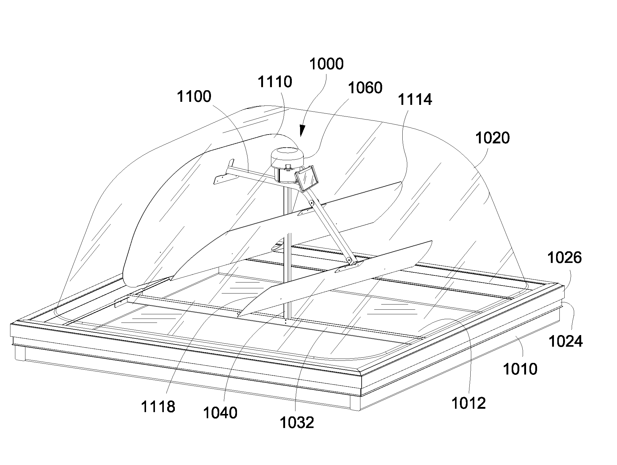
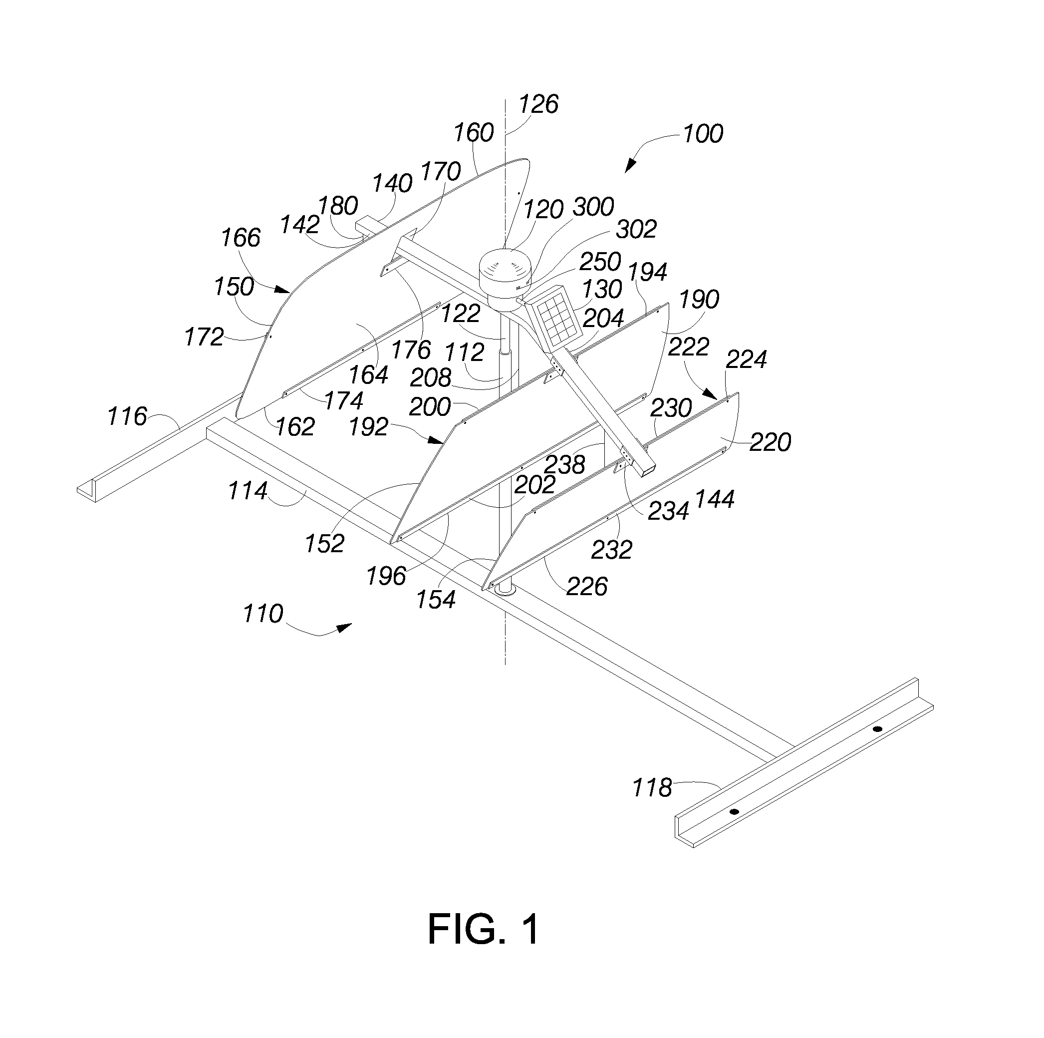
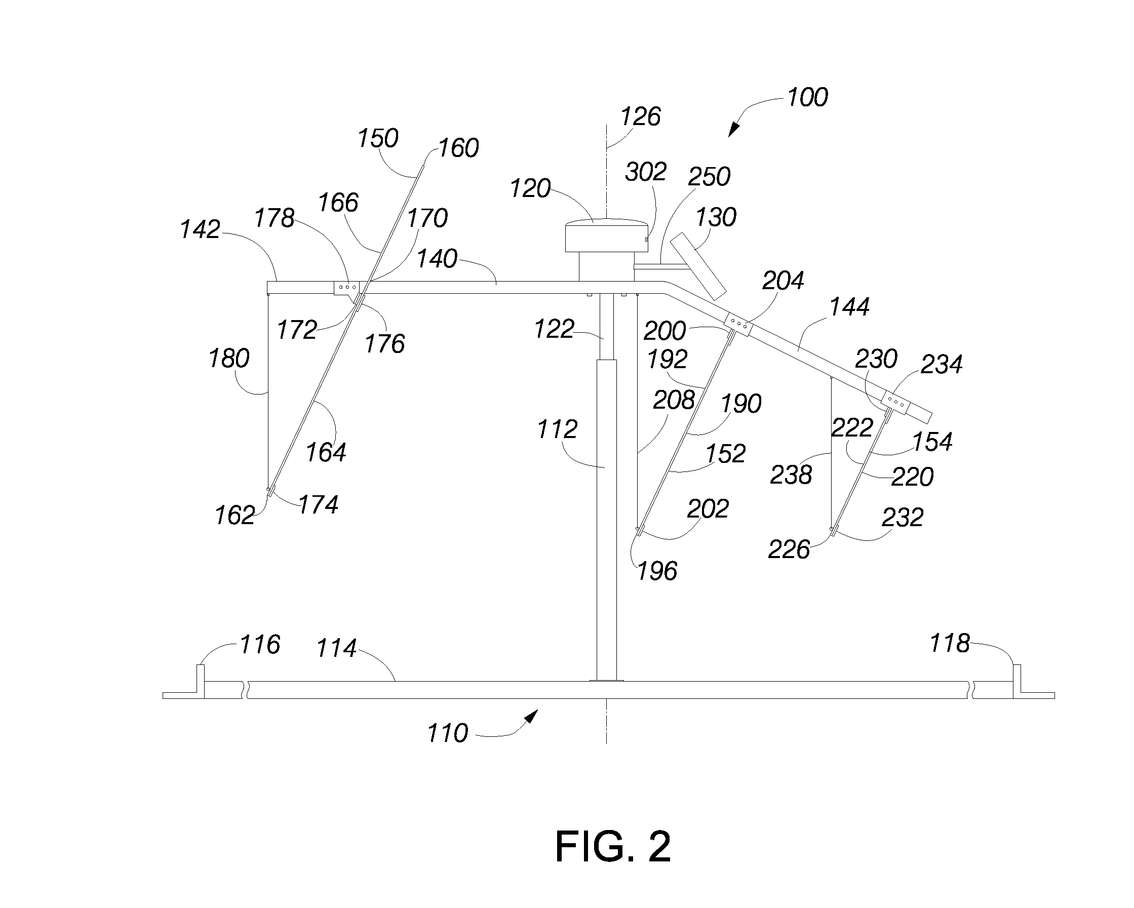
[0041]FIGS. 1-6 illustrate an embodiment of a solar tracking system 100. The solar tracking system includes a support structure 110, which comprises a vertical tube 112 mounted at the approximate midpoint of a horizontal beam 114. The beam includes a first mounting bracket 116 at one end and a second mounting bracket 118 at an opposite end. The mounting brackets are spaced apart by a distance corresponding to a distance across a conventional building skylight. Shorter or longer horizontal beams can be used for smaller or larger skylights. The support structure supports a control box 120 via a motor shaft 122 that extends vertically from the bottom of the control box. The lower end of the motor shaft is inserted into the upper end of the vertical tube as shown in FIG. 5. As shown in cross section in FIG. 3, a motor 124 within the control box causes the control box to rotate about a centerline 126 defined by the motor shaft.

[0042]A solar array 130 is coupled to the control box and rot...


PUM


Abstract

A solar tracking device is mounted above a skylight of a building. An array of mirrors is rotated at a rate of one revolution per day to reflect sunlight through the skylight. A control circuit intermittently adjusts the angular position of the tracking device so that the mirrors face the sun. A solar array charges an internal energy storage system so that no external power source is needed. The control circuit within the tracking device reduces the power requirements at night and when not moving the tracking device during the daytime to conserve electrical energy.

Description

RELATED APPLICATIONS[0001]The present application claims the benefit of priority under 35 USC § 119(e) to U.S. Provisional Application No. 60 / 803,362, filed on May 27, 2006.BACKGROUND OF THE INVENTION[0002]1. Field of the Invention[0003]The present invention is in the field of building interior illumination using reflected sunlight through an opening in the roof (e.g., a skylight).[0004]2. Description of the Related Art[0005]Skylights provide natural sunlight to interior locations of a building that receive little or no light via windows. Although passive skylights are adequate in some situations, generally such skylights only provide sufficient lighting when the sun is at or near its zenith. During the winter months, the sun is so low in the southern sky (assuming the building is in the northern hemisphere) that the lighting provided by a skylight is not sufficient even when the sun is at its zenith.[0006]Many mechanisms have been developed in response to the foregoing problem. For...

Claims


Application Information

Patent Timeline
IPC IPC(8): G02B17/00
CPCE04D13/033F21S11/00Y02B10/10G01S19/14F21V17/02
Inventor BRIEE, STEVENCHACE, ARTNER B.DAUNIS, EUGENE J.MALLORY, RAYNOR A.
Owner ECOMASTER CORP
Why Eureka
Try Eureka