Lens accessory mounting device

a technology for mounting devices and lenses, which is applied in the direction of mountings, instruments, cameras, etc., can solve the problems of deteriorating the outward appearance of the lens barrel or the camera to which the lens barrel is mounted, limiting the design of the lens cap to the front end of the lens barrel, and affecting the appearance of the lens barrel. , to achieve the effect of improving the outward appearance of the lens barrel

Inactive Publication Date: 2007-12-27
RICOH IMAGING COMPANY
View PDF10 Cites 7 Cited by
  • Summary
  • Abstract
  • Description
  • Claims
  • Application Information

AI Technical Summary

Benefits of technology

[0007] The present invention provides a lens accessory mounting device for mounting a lens accessory to a lens barrel using a bayonet structure, wherein the lens accessory mounting device improves the outward appearance of the lens barrel.
[0008] The present invention further provides a lens accessory mounting device for mounting a lens accessory to a lens barrel using a bayonet structure, wherein the lens accessory mounting device prevents the diameter of the lens barrel from increasing even in a state where a lens hood is mounted to the lens barrel, to thereby make it possible for a normal lens cap to be attached to the front of the lens barrel to which the lens hood is mounted.
[0022] According to the present invention, since the inward bayonet lugs, which are used to mount a lens accessory such as a lens hood to the front end of the lens barrel, are provided on an inner peripheral surface of the front end of the lens barrel, the inward bayonet lugs are not exposed outwardly so as to deteriorate the outward appearance of the lens barrel, which improves outward appearance of the lens barrel. Moreover, in the case where the front end of the lens barrel includes a lens hood mounting ring (13) so that a lens hood (2) can be mounted to the lens barrel via the lens hood mounting ring, various restrictions on the design of the lens hood mounting ring are relaxed, which eases a design for a lens cap mounting structure. Furthermore, since the outer diameter of the lens accessory is substantially the same as the outer diameter of the front end of the lens barrel, mounting the lens accessory to the front end of the lens barrel does not increase the diameter of the lens barrel, and therefore, the normal lens cap which is supplied with the lens barrel can be attached to the front of the lens barrel regardless of whether or not the lens accessory is mounted to the lens barrel, which does not increase the elements of the lens system.

Problems solved by technology

Therefore, in a state where no lens hood is mounted to the lens barrel, the bayonet lugs on an outer peripheral surface of the lens barrel at the front end thereof are exposed, which deteriorates the outward appearance of the lens barrel or the camera to which the lens barrel is mounted.
Additionally, the structure of the bayonet lugs which project radially outwards from an outer peripheral surface of the lens barrel at the front end thereof limits the lens design at the front end of the lens barrel, and especially makes the design for mounting a lens cap to the front end of the lens barrel difficult.
However, in the case where this type of lens hood is mounted to the lens barrel with a bayonet structure, the outer diameter of the front end of the lens barrel (to which the lens hood is mounted) increases due to the lens hood, which makes it impossible to attach a normal lens cap, which is designed to be attached to the front end of the lens barrel, to the front of the lens barrel (i.e., the front end of the lens hood).

Method used


Image

  • Lens accessory mounting device
  • Lens accessory mounting device
  • Lens accessory mounting device

Examples


Embodiment Construction

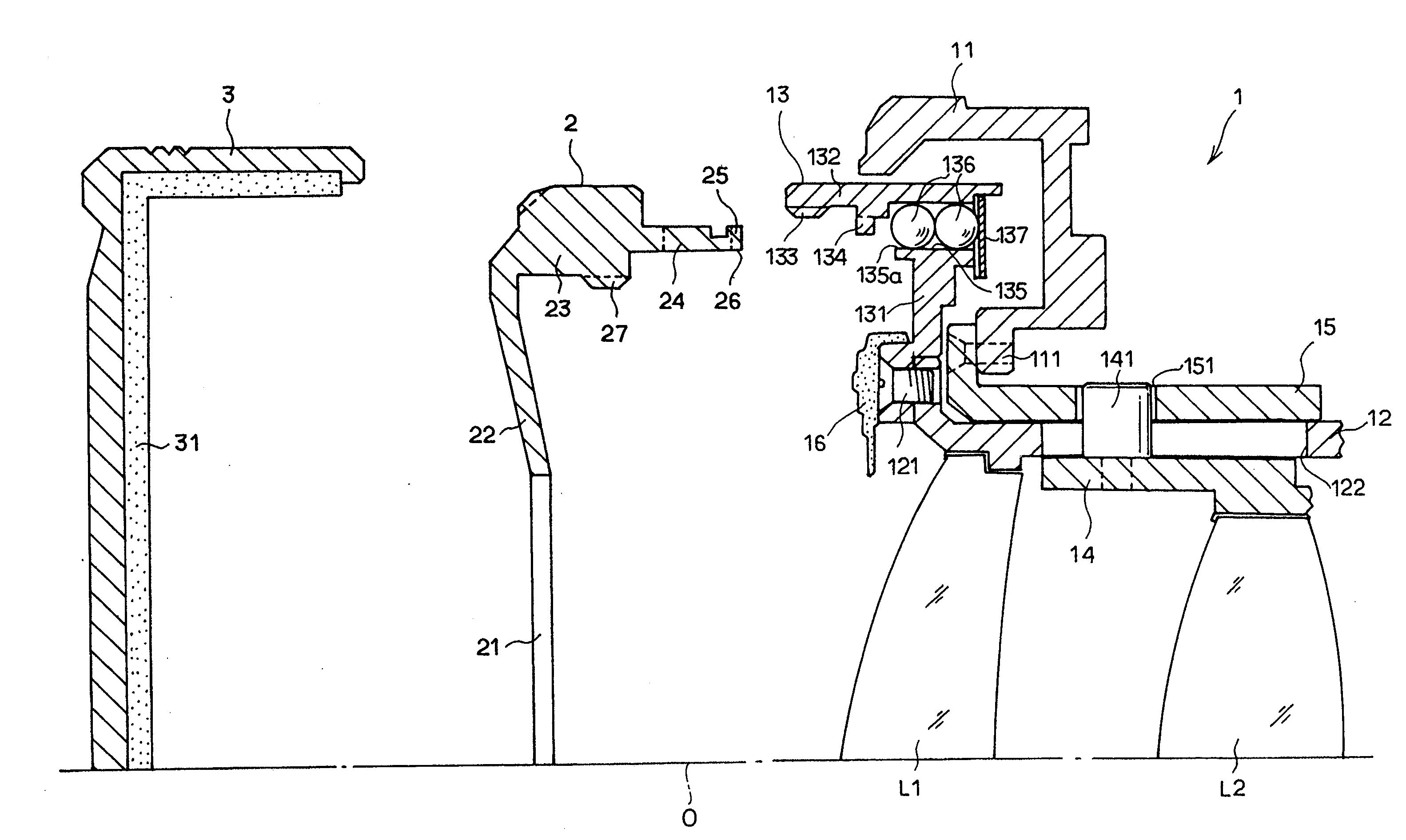
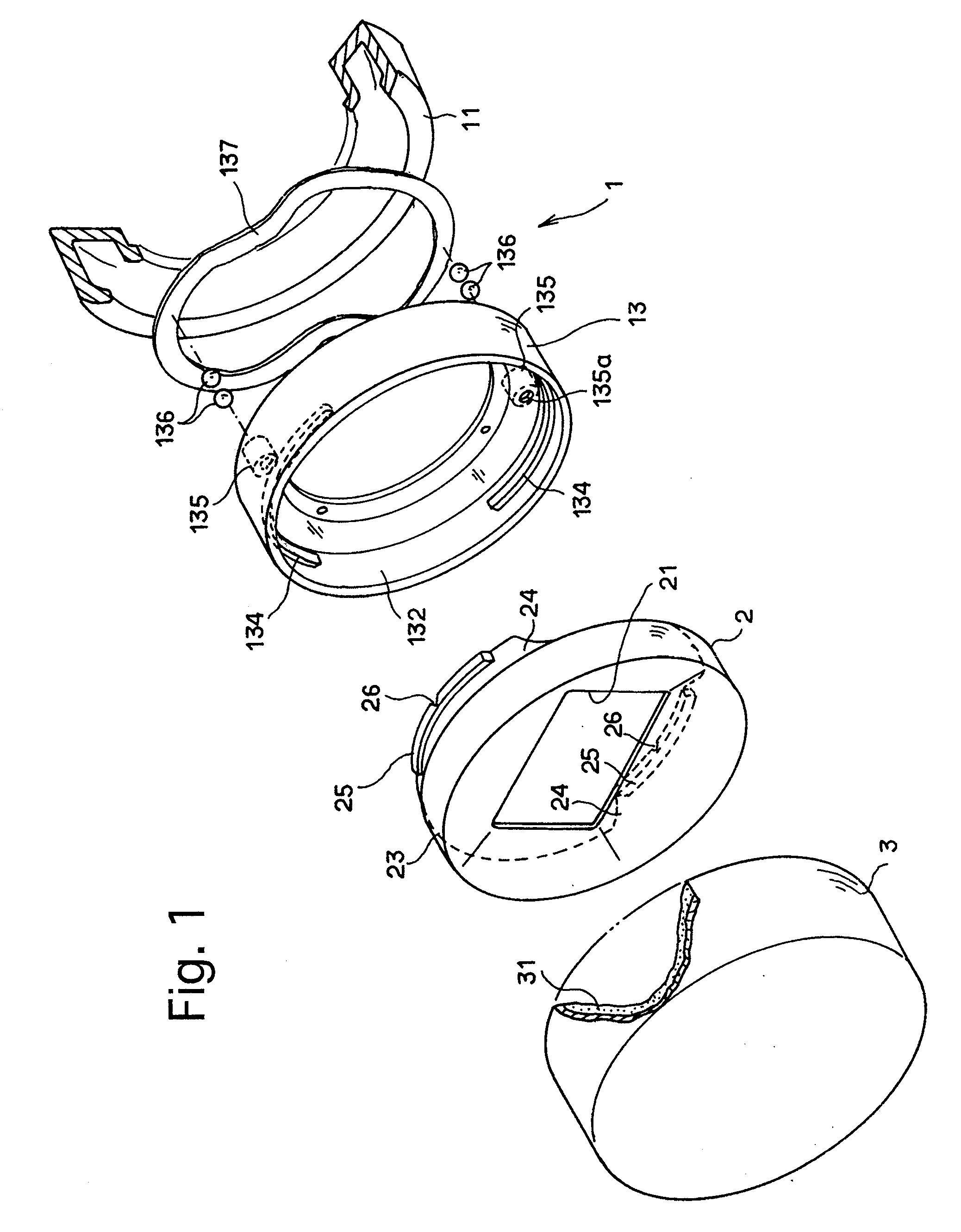
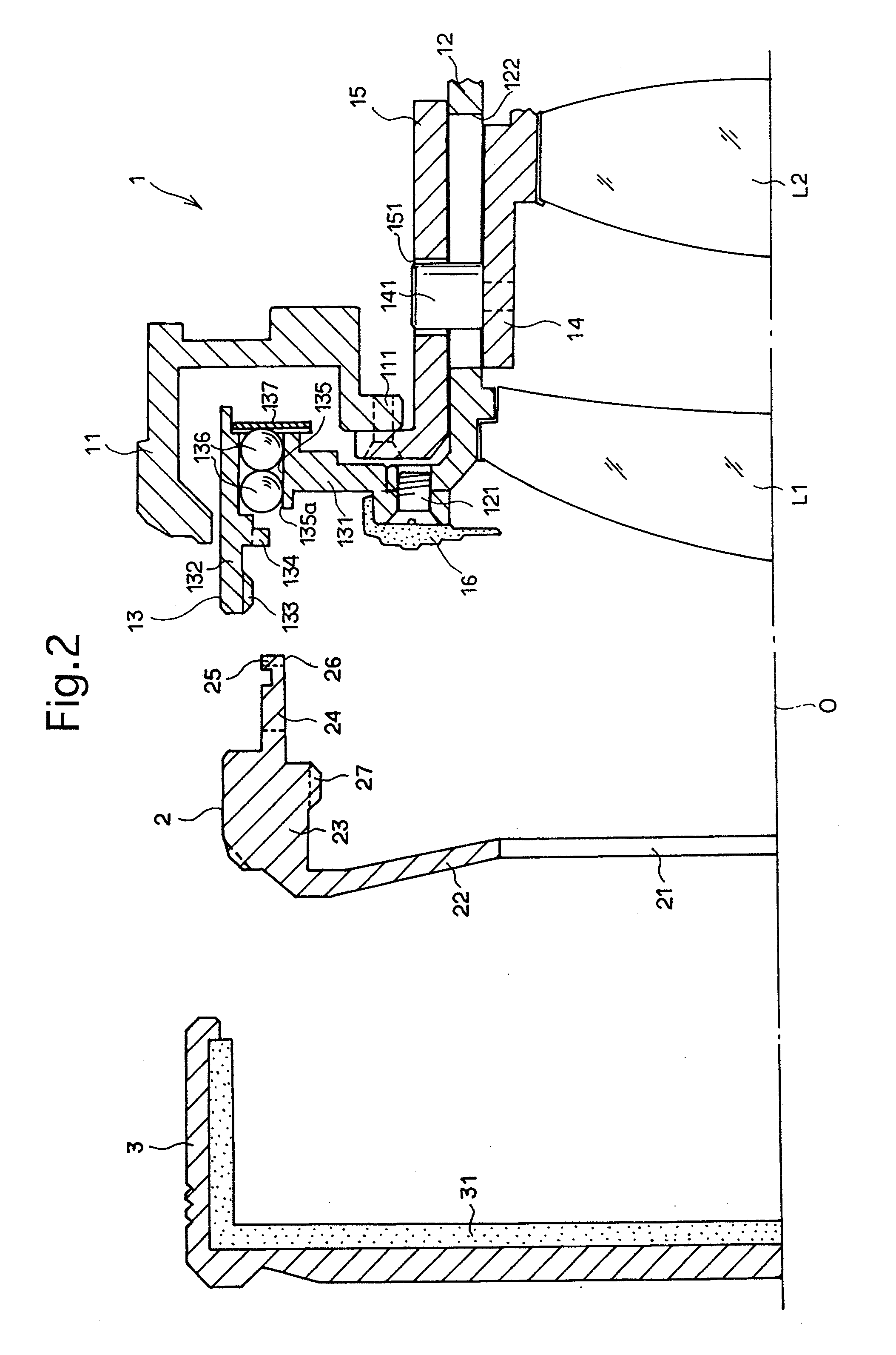
[0031]FIG. 1 shows a schematic view of an embodiment of a lens accessory mounting device according to the present invention which is applied to an interchangeable lens barrel 1 of a digital camera. The lens barrel 1 is provided at the rear end thereof (not shown in the drawings) with bayonet lugs (lens-side bayonet lugs) engageable with bayonet lugs (body-side bayonet lugs) on a lens mount of a camera body (not shown) to allow the lens barrel to be detachably attached to the camera body. This bayonet structure is the same as a conventional bayonet structure that is well-known in the art, so that the description thereof is omitted. The lens barrel 1 is provided around an outer peripheral surface thereof with a focus ring 11 together with a zoom ring (not shown). Manually rotating the focus ring 11 about an optical axis 0 of the lens barrel 1 causes a movable lens group L2 that serves as a focusing lens group to move in the direction of the optical axis 0 (optical axis direction) to b...


PUM


Abstract

A lens accessory mounting device for mounting a lens accessory to a front end of a lens barrel, an outer diameter of the lens accessory being substantially the same as an outer diameter of the front end of the lens barrel, the lens accessory mounting device includes at least one inward bayonet lug which projects radially inwards from an inner peripheral surface of a front end of the lens barrel; and at least one outward bayonet lug which projects radially outwards from the lens accessory to be engageable with the two inward bayonet lugs, respectively. The outward bayonet lug is firstly inserted into the front end of the lens barrel and subsequently brought into engagement with the inward bayonet lug, respectively, when the lens accessory is mounted to the lens barrel.

Description

BACKGROUND OF THE INVENTION [0001] 1. Field of the Invention [0002] The present invention relates to a lens accessory mounting device for mounting a lens accessory such as a lens hood, filter, etc., to a lens barrel of a camera. [0003] 2. Description of the Related Art [0004] Screw structures and bayonet structures have been conventionally used as devices for mounting a lens accessory such as a lens hood, a filter (optical filter), etc., to the front end of a lens barrel of a camera. The screw structure is composed of a female screw thread portion formed on an inner peripheral surface of a lens barrel at the front end thereof, and a male screw thread portion formed on an outer peripheral surface of the mounting portion of a lens accessory such as a lens hood or a filter so that the male screw thread portion is screw-engaged with the female screw thread portion when the lens accessory is mounted to the lens barrel. In such a screw structure, it is difficult to mount the lens accessor...

Claims


Application Information

Patent Timeline
Patent Type & Authority Applications(United States)
IPC IPC(8): G03B17/38
CPCG02B7/006G03B17/14G03B11/04G03B11/041
Inventor KOGURE, YUJISUZUKI, HIROAKI
Owner RICOH IMAGING COMPANY
Why Eureka
Try Eureka