Optical communication system with cats-eye modulating retro-reflector (MRR) assembly, the cats-eye mrr assembly thereof, and the method of optical communication

a technology of optical communication and retroreflector, which is applied in the direction of fibre transmission, multi-station light source, electrical apparatus, etc., can solve the problem that the optical aperture of the mrr cannot be too small, and achieve the effect of reducing the field of view

Inactive Publication Date: 2007-12-27
RABINOVICH WILLIAM +1
View PDF50 Cites 28 Cited by
  • Summary
  • Abstract
  • Description
  • Claims
  • Application Information

AI Technical Summary

Benefits of technology

[0007]The beam deflector is positioned at an optical aperture of the cats-eye MRR to coarsely deflect the received interrogating light beam to the focusing device of the cats-eye MRR. The beam deflector reduces the field of view (FOV) of the cats-eye MRR needed for intercepting an interrogating light beam from a transmitter without changing the operational FOV needed for the cats-eye MRR assembly to intercept the interrogating light beam from the transmitter. The beam deflector can comprise at least one of cascaded liquid crystal switchable prisms, MEMS based micromirror arrays that function as blazed gratings, or Risley prisms.

Problems solved by technology

The optical aperture of the MRR, however, cannot be too small as the amount of light retro reflected will be insufficient to close the link.

Method used


Image

  • Optical communication system with cats-eye modulating retro-reflector (MRR) assembly, the cats-eye mrr assembly thereof, and the method of optical communication
  • Optical communication system with cats-eye modulating retro-reflector (MRR) assembly, the cats-eye mrr assembly thereof, and the method of optical communication
  • Optical communication system with cats-eye modulating retro-reflector (MRR) assembly, the cats-eye mrr assembly thereof, and the method of optical communication

Examples


Embodiment Construction

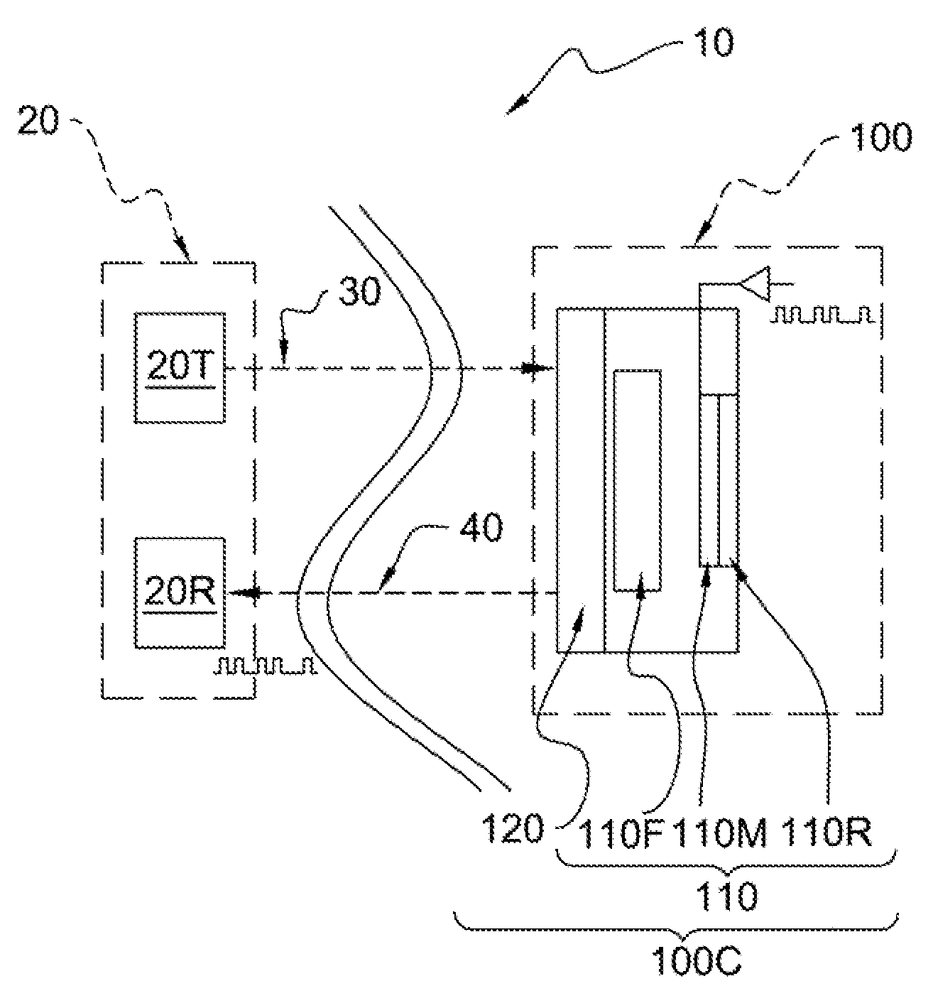
[0027]Referring to FIG. 1 an optical communication system 10 according to an embodiment of the present invention includes a base station or first terminal 20 and a remote or distal station or second terminal 100. The first terminal 20 can include a transmitter 20T and a receiver 20R. The transmitter 20T transmits an interrogating light beam 30) such as a CW beam, to the second terminal 100 and the receiver 20R receives the interrogating light beam 40 that has been modulated and retro-reflected at the second terminal 100. The second terminal 100 can include a cats-eye modulating retro-reflector (MRR) assembly 100C, which includes a cats-eye MRR 110. The assembly 100C also includes a beam deflector 120 for coarsely deflecting or steering the interrogating light beam 30 from the transmitter 20T to the cats-eye MRR 10. The assembly 100C also can include an angle of arrival sensor 130. See FIGS. 11 and 12.

[0028]The cats-eye MRR 110 can include an optical focusing device 110F, a light mod...


PUM


Abstract

An optical communicating system and method thereof includes first and second terminals. The first terminal has a transmitter for transmitting an interrogating light beam and a receiver for receiving the interrogating light beam. The second terminal has a cats-eye modulating retroreflector (MRR), which includes a modulator for modulating the interrogating light beam received from the transmitter an optical focusing device for focusing the interrogating light beam from the transmitter to the modulator, and a reflector for reflecting the modulated light beam to the receive. It can include a beam deflector positioned at the aperture of the optical focusing device of the catseye MRR to reduce the field of view of the cats-eye MRR, It can also include an angle of arrival sensor for sensing the angle of arrival of the interrogating beam at the second terminal. One or more pixels of the modulator can be activated to permit the activated pixel(s) to modulate the interrogating beam, which is reflected back to the receiver, and the beam deflector both can be controlled based on the angle of arrival detected

Description

BACKGROUND[0001]A modulating retro-reflector (MRR) is a device that allows free space optical communication without any pointing or tracking at a remote or distal end of the link. The MRR typically includes passive optical retro reflectors coupled with electro-optic modulators to allow long-range, free-space optical communication with a laser, and a pointing or acquisition or tracking system required only at one end of the link. In operation, the one end of the communication link includes a conventional free space optical communication terminal with an interrogator for illuminating the MRR on the remote or other end of the link with a continuous wave (CW) beam, The MRR imposes a modulation on the interrogating CW beam and passively retro reflects it back to the interrogator. The above types of systems are attractive for asymmetric communication links where one end of the link cannot afford the weight, power, or expense of a conventional free space optical communication terminal.[000...

Claims


Application Information

Patent Timeline
Patent Type & Authority Applications(United States)
IPC IPC(8): H04B10/00
CPCH04B10/2587
Inventor RABINOVICH, WILLIAMGILBREATH, G. CHARMAINE
Owner RABINOVICH WILLIAM
Why Eureka
Try Eureka