Drill stop sleeve for a dental drill, dental drill device with a drill stop sleeve, and set containing several drill stop sleeves

a technology of stop sleeve and drill stop, which is applied in the direction of dental tools, diagnostics, and drilling tools, can solve the problems of obstructing the view, obstructing the drilling hole, and complicated production and therefore expensive, so as to achieve the effect of improving the view of the drilling hol

Inactive Publication Date: 2007-12-27
STRAUMANN HLDG AG
View PDF15 Cites 32 Cited by
  • Summary
  • Abstract
  • Description
  • Claims
  • Application Information

AI Technical Summary

Benefits of technology

[0006] In accordance with one embodiment, a transparent or translucent design of the drill stop sleeve means that the view of the drilled hole can be decisively improved, without having to reduce the wall thickness of the drill stop sleeve and therefore the size of the abutment surface.

Problems solved by technology

A disadvantage of the drill stop sleeve according to this prior art has proven to be that the view of the drilled hole is partially obstructed by the drill stop sleeve, in particular just before the abutment surface reaches the bone or the tissue or material surrounding the drilled hole.
A further disadvantage has proven to be that several finger-like clamp elements are formed in the clamp area, making production complicated and therefore expensive.
Another disadvantage has proven to be that the drill stop sleeve has the greatest external diameter in the clamp area, which also obstructs the view.

Method used


Image

  • Drill stop sleeve for a dental drill, dental drill device with a drill stop sleeve, and set containing several drill stop sleeves
  • Drill stop sleeve for a dental drill, dental drill device with a drill stop sleeve, and set containing several drill stop sleeves
  • Drill stop sleeve for a dental drill, dental drill device with a drill stop sleeve, and set containing several drill stop sleeves

Examples


Embodiment Construction

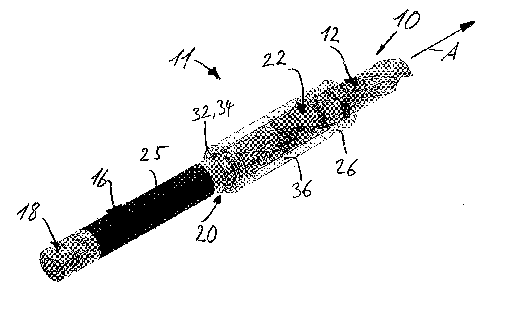
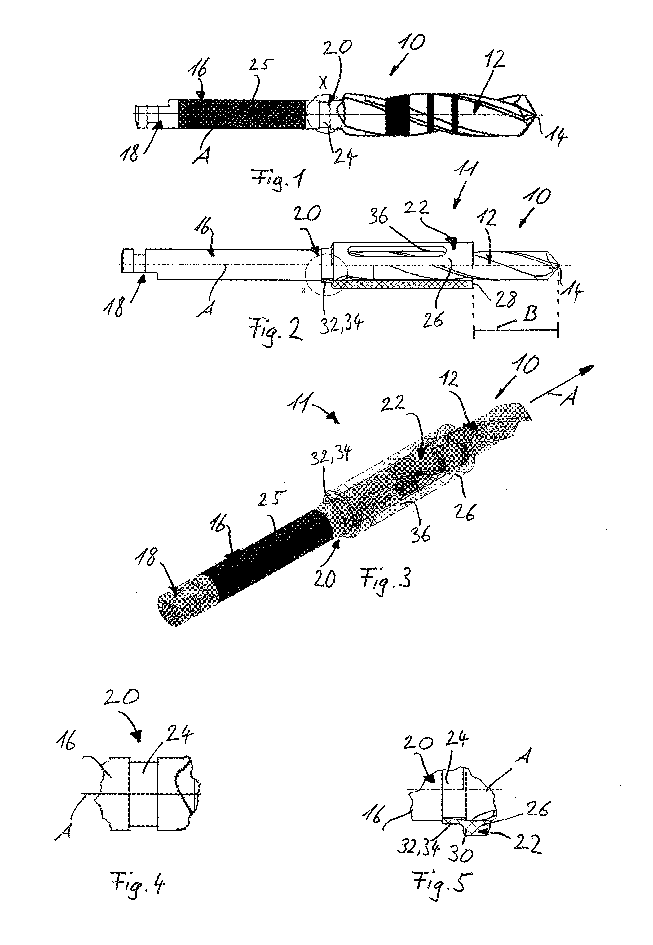
[0044] Two illustrative embodiments of a dental drill 10 are shown in FIGS. 1-3. The dental drill 10 comprises, on the one hand, a cutting part 12 with a drilling end 14, and, on the other hand, a shank part 16 with an exposed receiving end area 18. The receiving end area 18 is intended to be received in a generally known drill holder device and has a rotary securing means configured as a surface, and an axial securing means designed as a groove extending in the circumferential direction. The rotary securing means and the axial securing means ensure that the dental drill 10 can be brought into a fixed connection with the drill holder device, which for example is part of a drill drive or of a hand drill.

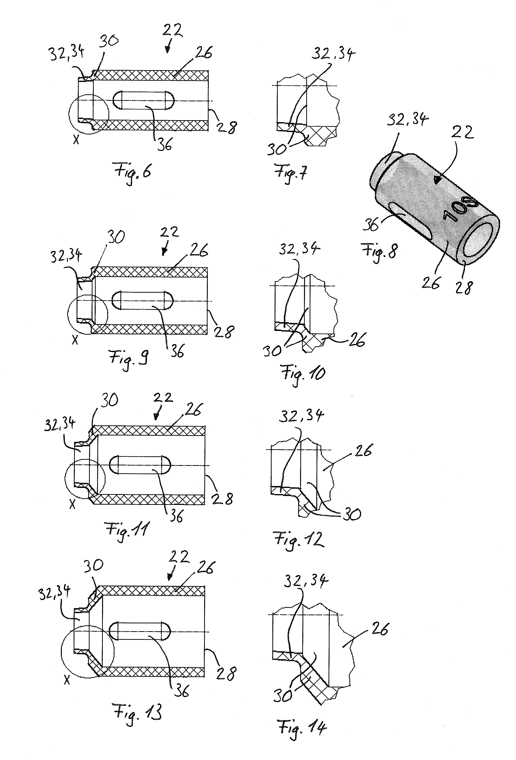
[0045] At a distance from the cutting part 12, the shank part 16 has a holding area 20 for a drill stop sleeve 22 (see FIGS. 2 and 3). As FIGS. 4 and 5 in particular show, a completely circumferential groove 24 is formed in the shank part 16 in this holding area 20. This groove 24 ha...


PUM

PropertyMeasurementUnit
transparentaaaaaaaaaa
translucentaaaaaaaaaa
areaaaaaaaaaaa

Abstract

A dental drill (10) defining a bore diameter and a drill stop sleeve (22) which is transparent or translucent, thereby improving the view of the drilled hole formed by the drilling during the operation. The drill stop sleeve (22) comprises an uninterrupted circumferential lip (34), which interacts with a groove (24) formed in the shank part (16) of the dental drill (10) and thus fixes the drill stop sleeve (22) on the dental drill (10). The drill stop sleeves (22) of equal length are held in a blister of a set, the blister having, for each drill stop sleeve (22), a specific receiving recess that is closed in a sterile manner. Each blister comprises several drill stop sleeves with sleeve diameters corresponding to the bore diameters.

Description

FIELD OF THE INVENTION [0001] The present invention relates to a drill stop sleeve, a dental drill device, and to a set containing several drill stop sleeves. BACKGROUND [0002] A drill stop sleeve and a dental drill device comprising a dental drill and a drill stop sleeve are known from U.S. Pat. No. 6,514,258 B1. Said document discloses a dental drill that has a drilling end and a cylindrical shank part. At an end area of the shank part directed toward the drilling end, it is provided with a cuff-like thickened area that has a greater diameter than the bore diameter of the dental drill. At one of its end faces, the drill stop sleeve has an abutment surface and, adjoining the other end face, a clamp area intended to engage around the thickened area. In the clamp area, the drill stop sleeve has the greatest external diameter, which is formed by several resilient clamp fingers. These are formed by gaps extending in the longitudinal direction of the drill stop sleeve and open at the en...

Claims


Application Information

Patent Timeline
Patent Type & Authority Applications(United States)
IPC IPC(8): A61C3/02
CPCA61B17/1617A61B17/176A61B19/0256A61B19/026A61B2019/0219A61B2019/0258Y10T408/8925A61B2019/306A61B2019/446A61C1/084B23B49/005B23B51/02B23B2270/36A61B2019/0278A61B2050/0065A61B50/22A61B50/20A61B50/30A61B2050/3008A61B2090/036A61B90/94
Inventor HIRSCH, ERIKANAF, PATRICK
Owner STRAUMANN HLDG AG
Why Eureka
Try Eureka