
Bone fixation device

a bioabsorbable, bone technology, applied in the direction of prosthesis, medical science, surgery, etc., can solve the problems of poor rotational stability of a bone fragment fixed with a smooth, poor strength properties of perpendicular materials, poor rotational stability of a cylindrical pin, etc., to achieve good rotational stability, good bone fragment fixation, and high pull-out load carrying capacity

Active Publication Date: 2007-12-27
BIORETEC
View PDF18 Cites 29 Cited by
  • Summary
  • Abstract
  • Description
  • Claims
  • Application Information

AI Technical Summary

Benefits of technology

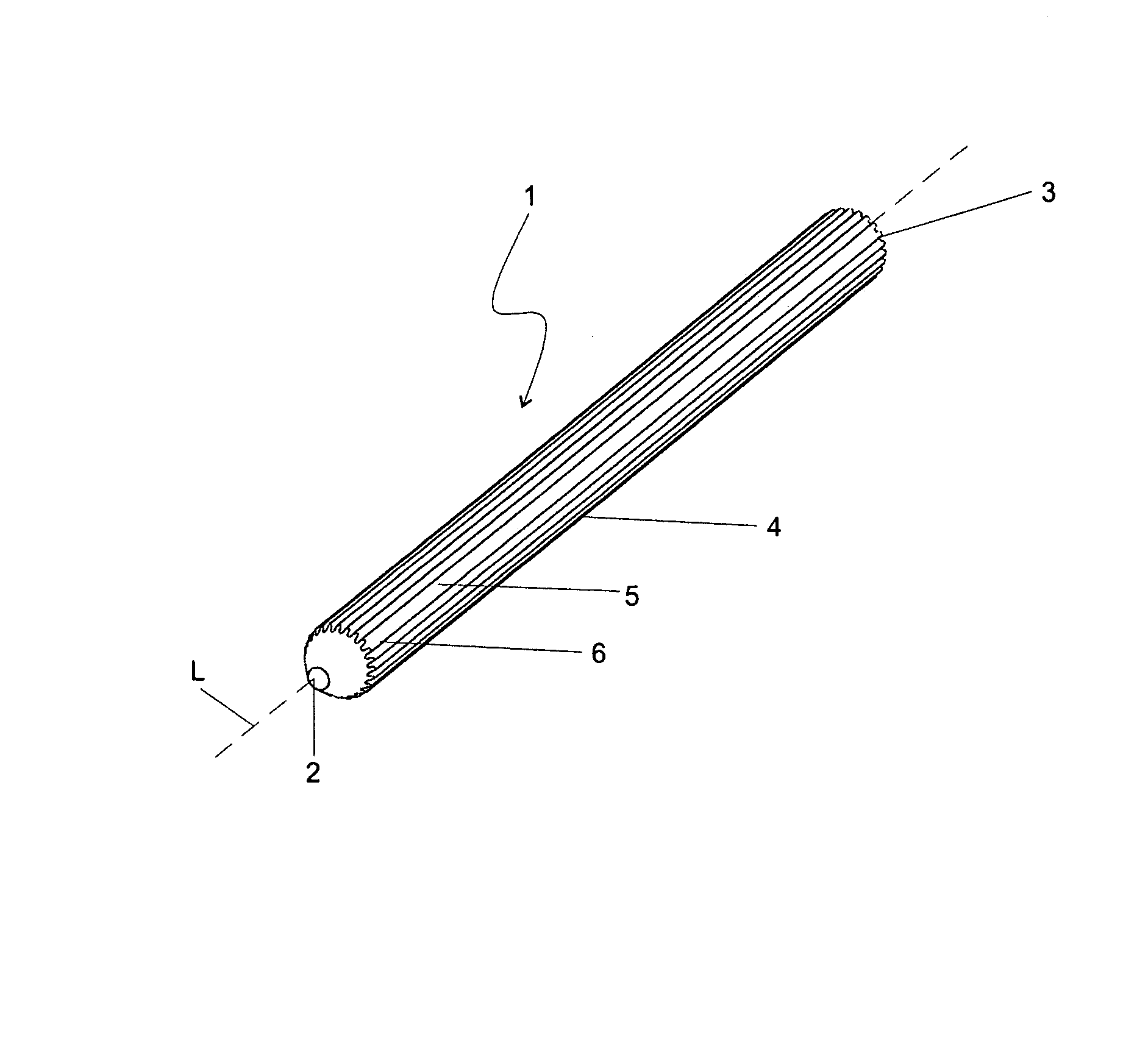
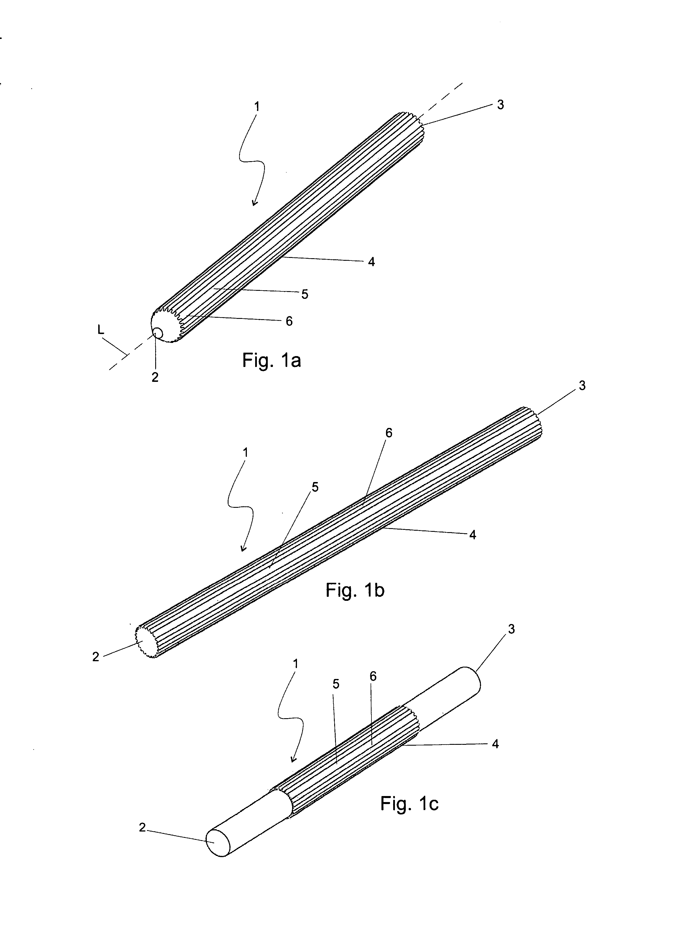
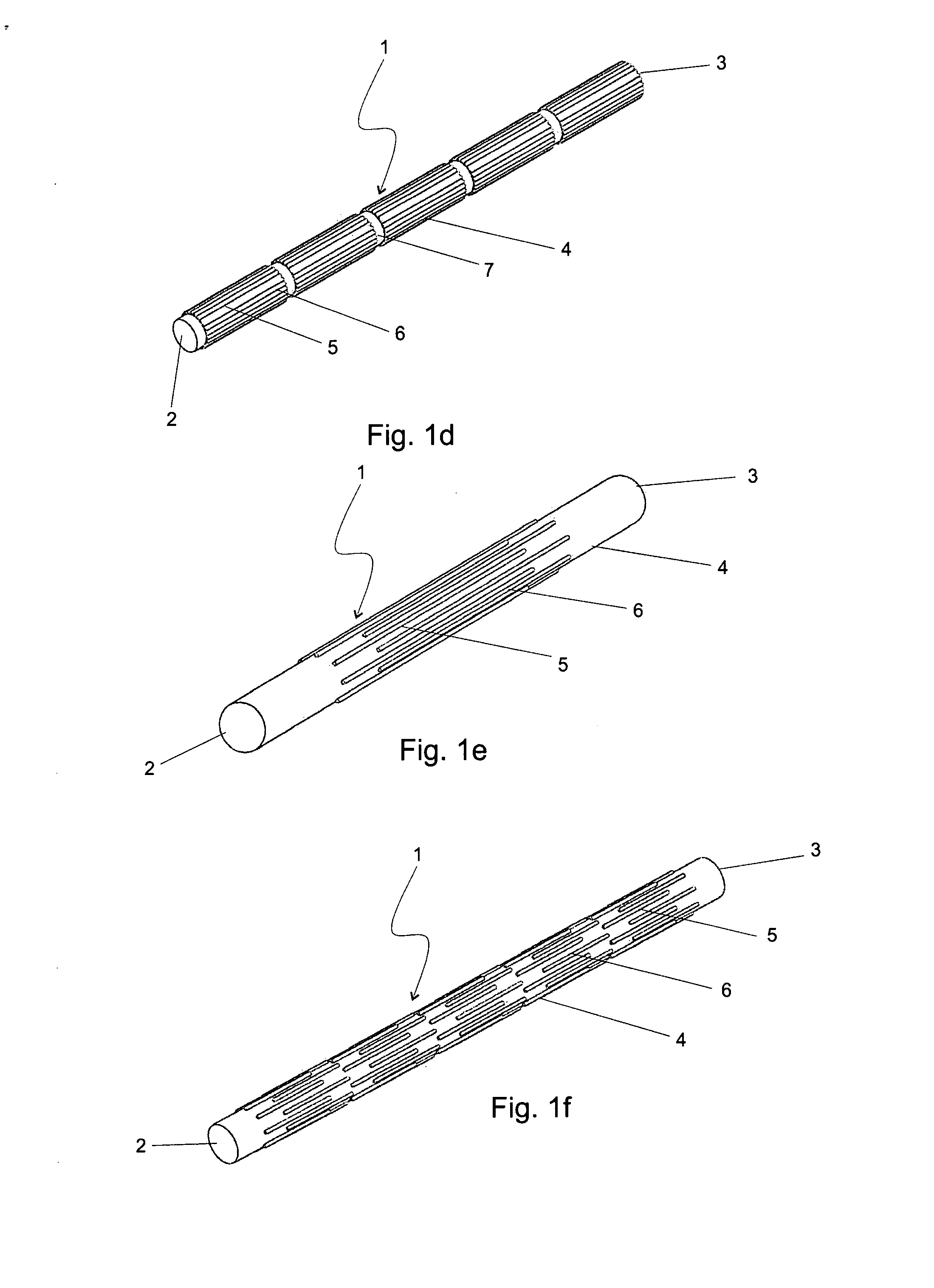
[0011] The invention provides a bone fracture fixation device, such as a pin or a tack, which has a deformable grooved and ridged surface structure and shape so that it can be pushed into a drillhole whose diameter is even smaller than the maximum transverse shaft diameter of-the pin or the tack to achieve a good, tight fixation of a bone fragment. The bone fracture fixation device is strong and tough and has a high pull-out load carrying capacity. It also gives good rotational stability for the fixed bone fragment.
[0012] The bone fracture fixation device swells in vivo slightly in the direction transverse to its longitudinal axis. The swelling also increases the fixation strength of the fixation device—fixed bone system. The diameter of the fixation device increases at least within first six weeks, preferably at least within first two weeks and most preferably within first 63 hours in a test in vitro.
[0013] Further, it can be concluded that the fixation device of the invention promotes the healing process of a bone fracture. Because the fixation device comprises grooves and ridges on the surface of its shaft, small canals are formed between the bottoms of the grooves and the bony wall surrounding the drillhole. The small canals enhance the circulation of blood and tissue fluids and thus the healing of the fracture takes place more rapidly. BRIEF DESCRIPTION OF THE INVENTION

Problems solved by technology

(Partially) fibrillated materials have good strength properties in the direction of drawing, but these materials have poor strength properties in the direction perpendicular to the drawing direction, because longitudinal fibrils easily separate from each other.
Pin with a solid cylinder structure needs a drillhole of specific size, because too large a drillhole gives a loose pin fixation and too small a drillhole prevents totally the insertion of a cylindrical pin.
Additionally, the rotational stability of a bone fragment fixed with one smooth, cylindrical pin is poor.

Method used


Image

  • Bone fixation device
  • Bone fixation device
  • Bone fixation device

Examples


example

Tests Carried Out with the Fixation Device

[0069] Identification of the Test Samples

[0070] The test samples were pins manufactured by Bioretec Oy, said pins having a nominal diameter of 1.5 mm (LOT 051222 manufactured in December 2005 in the Bioretec production facility). The raw material of the pins was 85L / 15G PLGA, with inherent viscosity of 5.5 dl / g (Boehringer Ingelheim GmbH, Germany), and the pins were gamma sterilized (Gamma-Service Produktbestrahlung GmbH, Germany). PLGA is a copolymer of L-lactide and glycolide, the amount of L-lactide was 85 wt.-% and the amount of glycolide was 15 wt.-%.

[0071] The pins were manufactured by melt extruding a longitudinal, cylindrical billet. The billet was uniaxially oriented in a die drawing process following the extruding process. In the die drawing process the billet was formed into its final grooved cross sectional shape. Between extruding and drawing there may be time for the billet to cool down, or the billet is actively cooled betw...


PUM


Abstract

The present invention relates to a bioabsorbable osteosynthesis fixation device for the fixation of bone fractures or osteotomies. The fixation device comprises a tip (2), a shaft (4) and a head (3). The periphery of the shaft (4) comprises ridges (6) which extend in a direction which forms an angle with the longitudinal axis of the shaft, the angle being between −45° and 45°. The present invention also relates to a method for manufacturing the bioabsorbable osteosynthesis fixation device.

Description

FIELD OF THE INVENTION [0001] The present invention relates to a bioabsorbable osteosynthesis fixation device, such as a pin or a tack, and a method for manufacturing a fixation device. [0002] More precisely, the invention relates to an osteosynthesis fixation device made of a bio-compatible material which is entirely absorbable in vivo. The fixation device is in a form of, an elongated object. It exhibits sufficient mechanical properties to provide efficacious and reliable support to, for example, a traumatized skeleton, for a sufficiently long period of time to allow for consolidation and repair of bone fractures and / or osteotomies. It also exhibits good bioabsorbability, sufficient to avoid a second surgical intervention, such as is frequently required to remove metallic osteosynthesis devices. BACKGROUND OF THE INVENTION [0003] In surgery, it is known to employ implants manufactured of biodegradable (under tissue conditions absorbable) polymers for connecting tissues together, a...

Claims


Application Information

Patent Timeline
Patent Type & Authority Applications(United States)
IPC IPC(8): A61B17/58
CPCA61B17/0401A61B17/86A61B17/8625A61B17/863A61B17/864A61B17/8645A61B17/865A61B17/92A61B2017/00004A61B2017/00858A61B2017/00898A61L31/148A61B17/846A61B2017/8655A61B17/84A61B17/68A61L27/14A61L27/58
Inventor ALLINNIEMI, TIMOHEINO, HARRITORMALA, PERTTI
Owner BIORETEC
Learn More