Stent Graft Tapered Spring

a stent and spring technology, applied in the field of endoluminal stent grafts, can solve the problems of limited use restricted and significant axial bending and flexing of conventional stent grafts, and achieve the effect of avoiding restriction of flow through the body lumen

Active Publication Date: 2007-12-27
MEDTRONIC VASCULAR INC
View PDF15 Cites 26 Cited by
  • Summary
  • Abstract
  • Description
  • Claims
  • Application Information

AI Technical Summary

Benefits of technology

[0011] When properly positioned rotationally within a tortuous body lumen such that the smallest stent cells are placed along the inside radius of a curved segment of the tortuous body lumen, the tapered stent springs provide axial flexibility to the stent graft in at least one direction. Thus, the stent graft easily conforms to the curved segment of the tortuous body lumen while maintaining support for the lumen at the curved segment.
[0012] Accordingly, use of the stent graft avoids restriction of flow through the body lumen resulting from binding or kinking of the stent graft at curved segments of the body lumen.

Problems solved by technology

Thus, after deployment in a tortuous body lumen, conventional stent grafts were often subjected to significant axial bending and flexing.
Stent cell overlap caused binding or kinking of the stent graft 1 resulting in restriction of flow through the body lumen.
Accordingly, the use of conventional stent grafts was limited to certain applications that avoided damage to or destruction of the stent graft from excessive axial bending.

Method used


Image

  • Stent Graft Tapered Spring
  • Stent Graft Tapered Spring
  • Stent Graft Tapered Spring

Examples


Embodiment Construction

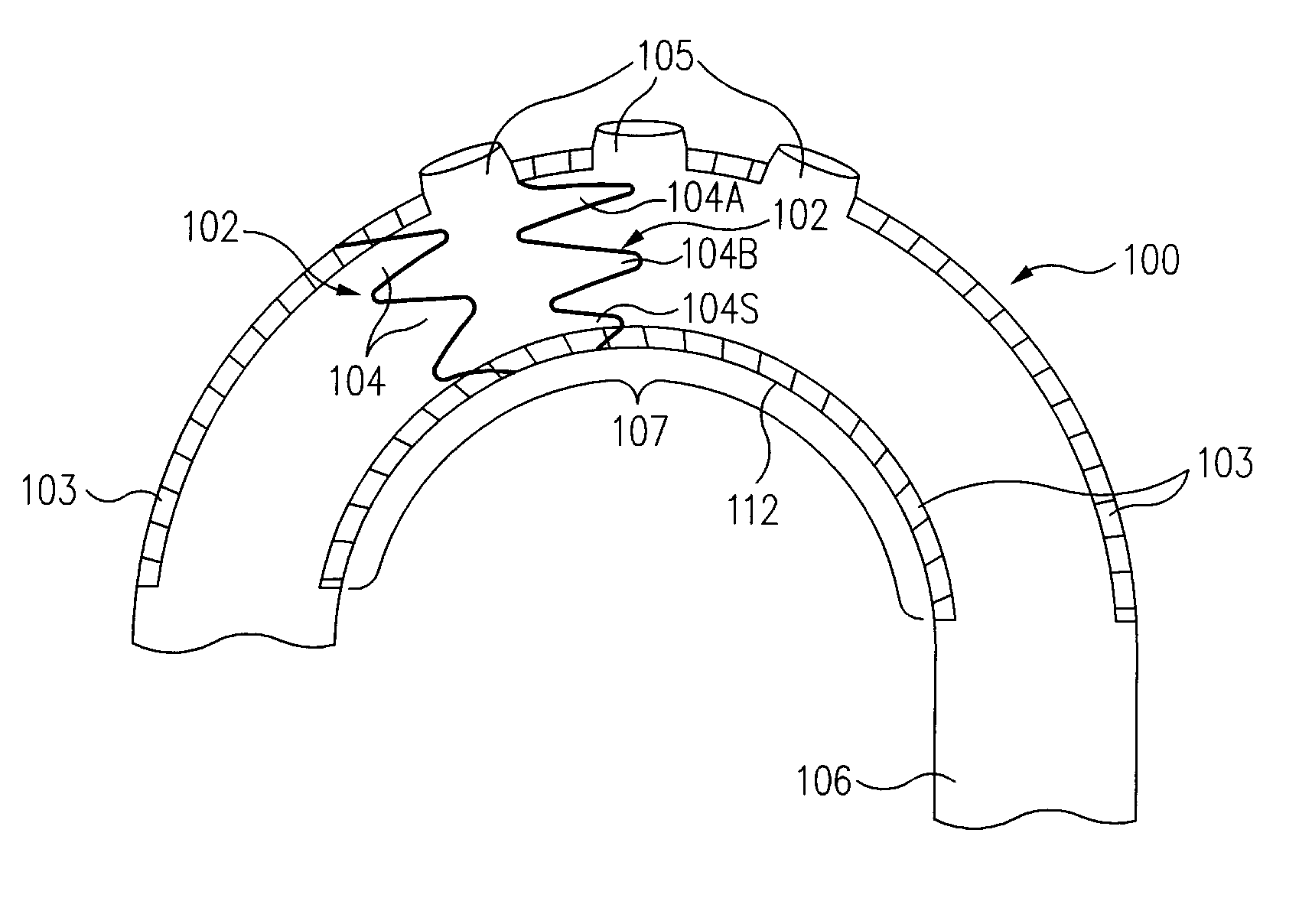
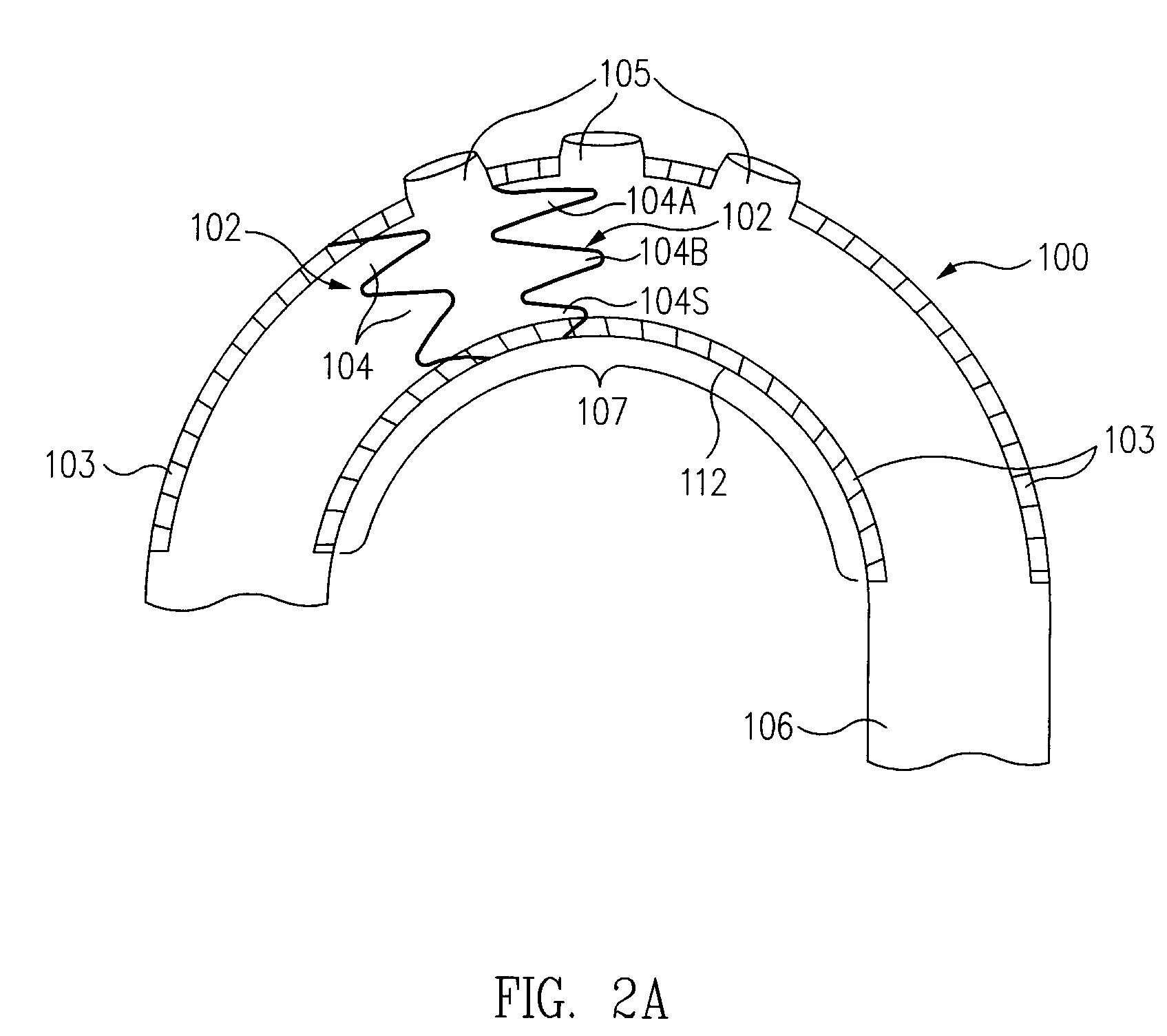
[0023] Stent graft 100 (FIG. 2A) includes a plurality of spaced apart tapered stent springs 102 coupled to a cylindrical shape stent graft material 103. A tortuous body lumen, such as an artery system 106, in which stent graft 100 is deployed, includes a curved segment, e.g., a thoracoabdominal aortic arch 107, which is diseased or damaged and which requires endoluminal prosthetic support. Thus, stent graft 100 is percutaneously inserted into artery system 106, transported transluminally to aortic arch 107, and deployed to support aortic arch 107.

[0024] As shown, in one embodiment, stent graft material 103 may define one or more perimeter openings 105, (fenstrations), that allow fluid flow through perimeter openings 105, out of stent graft 100, into other segments (not shown) of artery system 106.

[0025] Tapered stent springs 102 provide axial flexibility to stent graft 100 in at least one direction. Accordingly, stent graft 100 easily conforms to the curved shape of aortic arch 10...


PUM


Abstract

A stent graft includes a stent graft material of cylindrical shape and tapered stent springs coupled to the stent graft material. Each stent spring includes a first stent cell and a second stent cell contiguous with the first stent cell. The first stent cell and the second stent cell are coupled. The second stent cell of each tapered stent spring is smaller than the first stent cell thereby defining a tapered shape to the tapered stent springs. The stent graft is placed in a curved segment of a tortuous body lumen and rotationally positioned such that the smallest stent cell of each tapered stent spring is placed at an inside radius of the curved segment.

Description

BACKGROUND OF THE INVENTION [0001] 1. Field of the Invention [0002] The present invention relates to endoluminal structures. More particularly, the present invention relates to endoluminal stent grafts for use in curved body lumens. [0003] 2. Description of the Related Art [0004] A conventional stent graft typically includes a radially expandable stent, formed from a plurality of uniform annular stent springs, and a cylindrical shape graft material to which the stent springs are coupled. Stent grafts are well known for use in reinforcing or holding open the interior wall of a generally tubular shape human vascular and other body lumen. [0005] At deployment, after percutaneous insertion and transluminal transport to the point of use within a damaged or diseased body lumen, e.g., an aneurysmal artery, the stent graft is radially expanded. A stent graft is self-expandable or expandable by application of pressure applied outwardly to the interior portion of the stent graft. After deploy...

Claims


Application Information

Patent Timeline
Patent Type & Authority Applications(United States)
IPC IPC(8): A61F2/06A61F2/82
CPCA61F2/07A61F2002/061A61F2002/075A61F2250/0029A61F2/90A61F2002/826
Inventor BERRA, HUMBERTOLETORT, MICHEL
Owner MEDTRONIC VASCULAR INC
Why Eureka
Try Eureka