
Concrete pole base cover

Inactive Publication Date: 2008-01-03
MCGLINCH BRADLEY J
View PDF10 Cites 21 Cited by
  • Summary
  • Abstract
  • Description
  • Claims
  • Application Information

AI Technical Summary

Benefits of technology

[0004]Accordingly, the present invention provides a cover for a concrete pole base that may be mounted on the base after the base is installed in the ground. The cover is made from a material that is not subject to rusting and, preferably, also not subject to staining or that can at least be washed to remove any dirt or debris that may adhere to the outer surface of the cover to maintain the overall aesthetic appearance of the pole and base.
[0009]An additional feature that may be provided includes an outwardly extending flange, which is provided at the open lower end of the cylinder-shaped wall. The flange projects outwardly from said cylinder-shaped wall to form a perimeter flange or skirt around the cylinder-shaped wall. For example, the skirt may discourage the growth of grass around the outer perimeter of the cylinder-shaped wall. The flange may include an upwardly extending lip, which extends into the open lower end of the cylinder-shaped wall between the concrete base and the cylinder-shaped wall to thereby anchor the flange about the concrete base with the cylinder-shaped wall.
[0015]In yet another form of the invention, a concrete pole base cover includes a cylinder-shaped wall, with an open upper end and an open lower end, and an upper wall that at least partially closes the open upper end of the cylinder-shaped wall. The upper wall includes an opening for receiving the post of a pole assembly. The cylinder-shaped wall has an inner diameter and a height sized to cover and enclose the concrete base that anchors the post to the ground. In addition, a skirt is provided that extends around the cylinder-shaped wall. For example, the skirt may discourage the growth of grass around the outer perimeter of the cylinder-shaped wall.
[0018]Accordingly, the present invention provides a cover for a concrete pole base, such as a concrete light pole base, that will protect the base from damage or corrosion due to sprinkler water, flying debris from lawn mowers, and will also cover defects or stains in the base.

Problems solved by technology

However, over time the appearance of these concrete bases tends to degrade from stains from either rust that accumulates at the pole mounting plate and / or the concrete anchor bolts that mount the pole to the concrete base or from iron deposits from sprinkler water distributed by sprinkler systems.

Method used


Image

  • Concrete pole base cover
  • Concrete pole base cover
  • Concrete pole base cover

Examples


Embodiment Construction

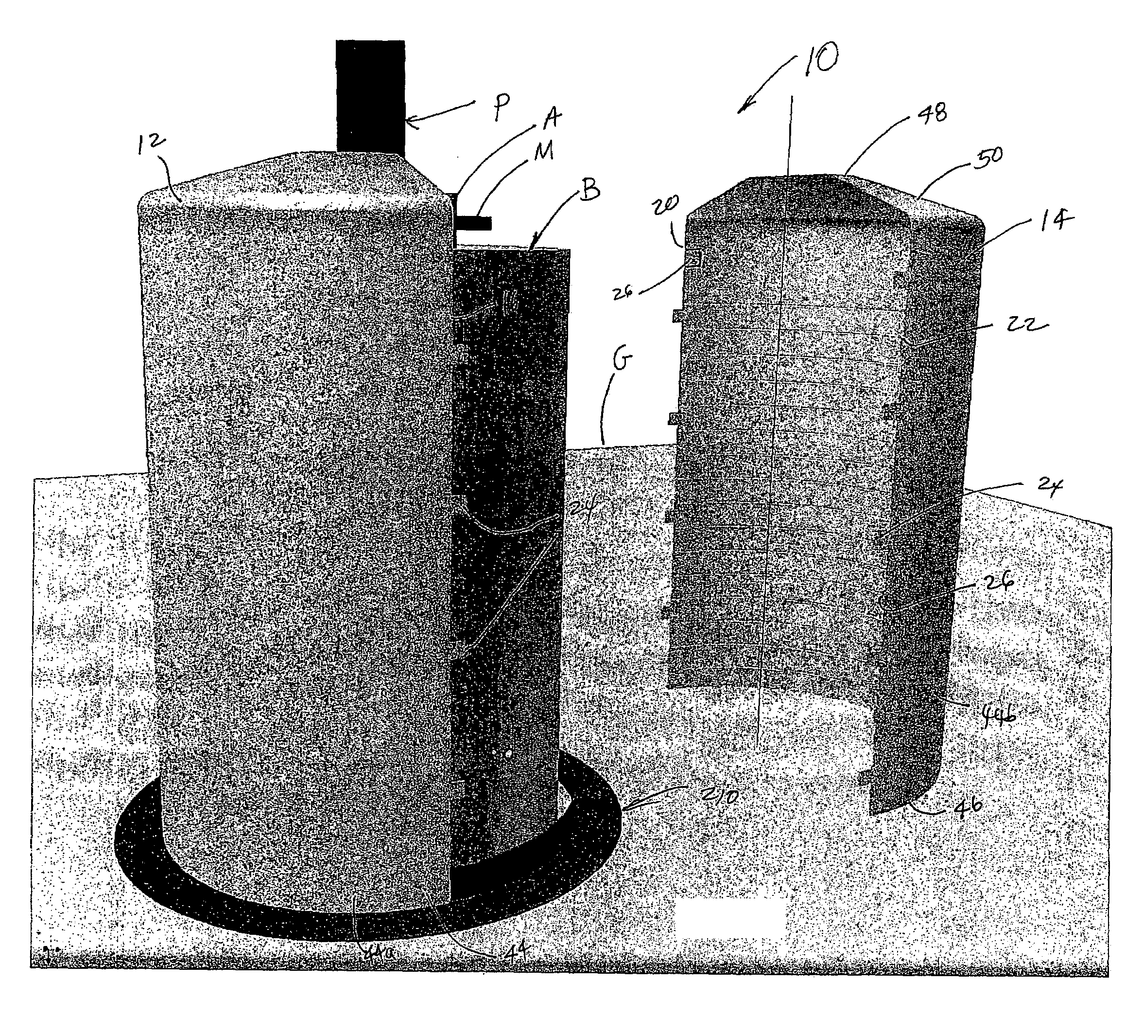
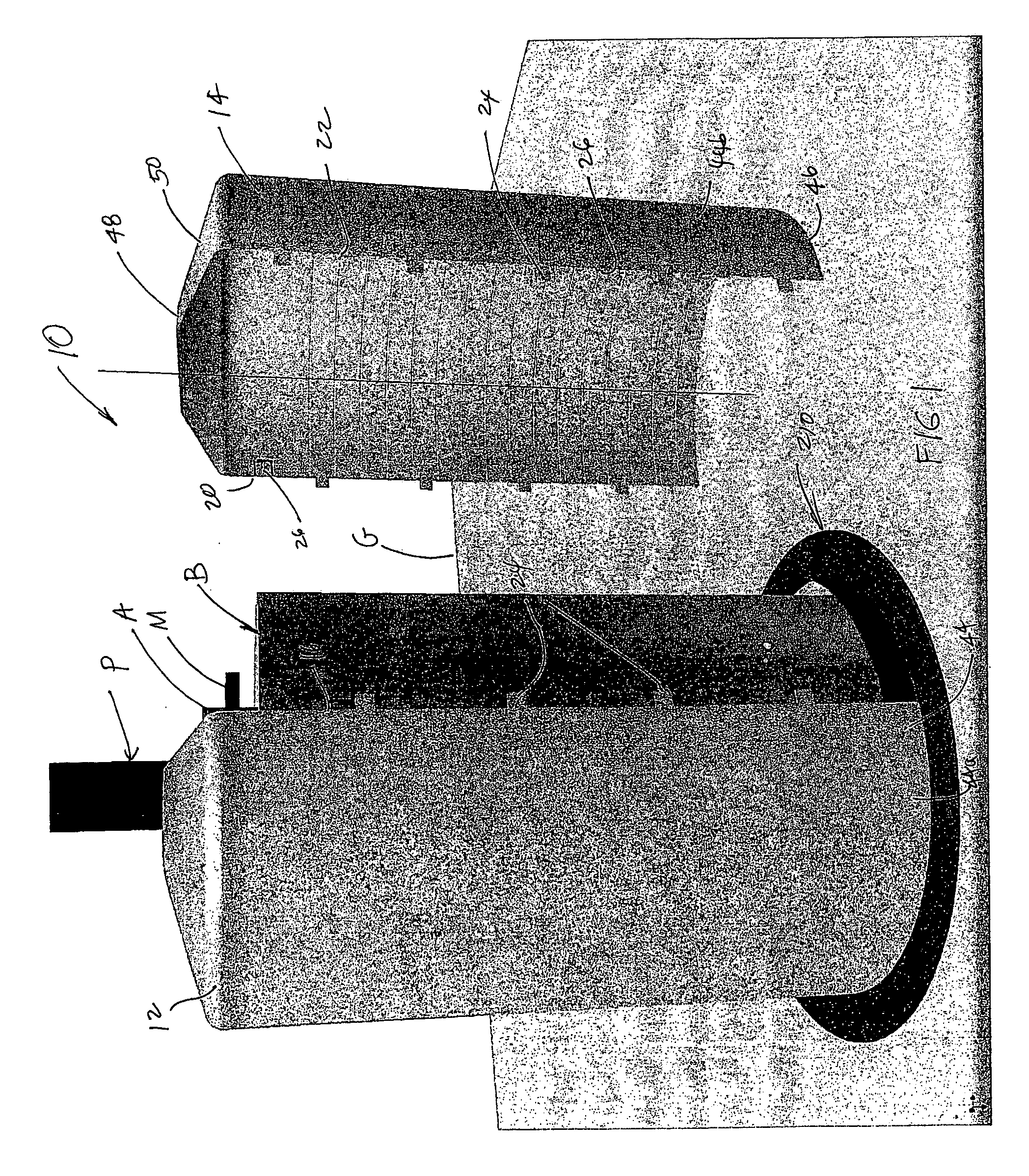
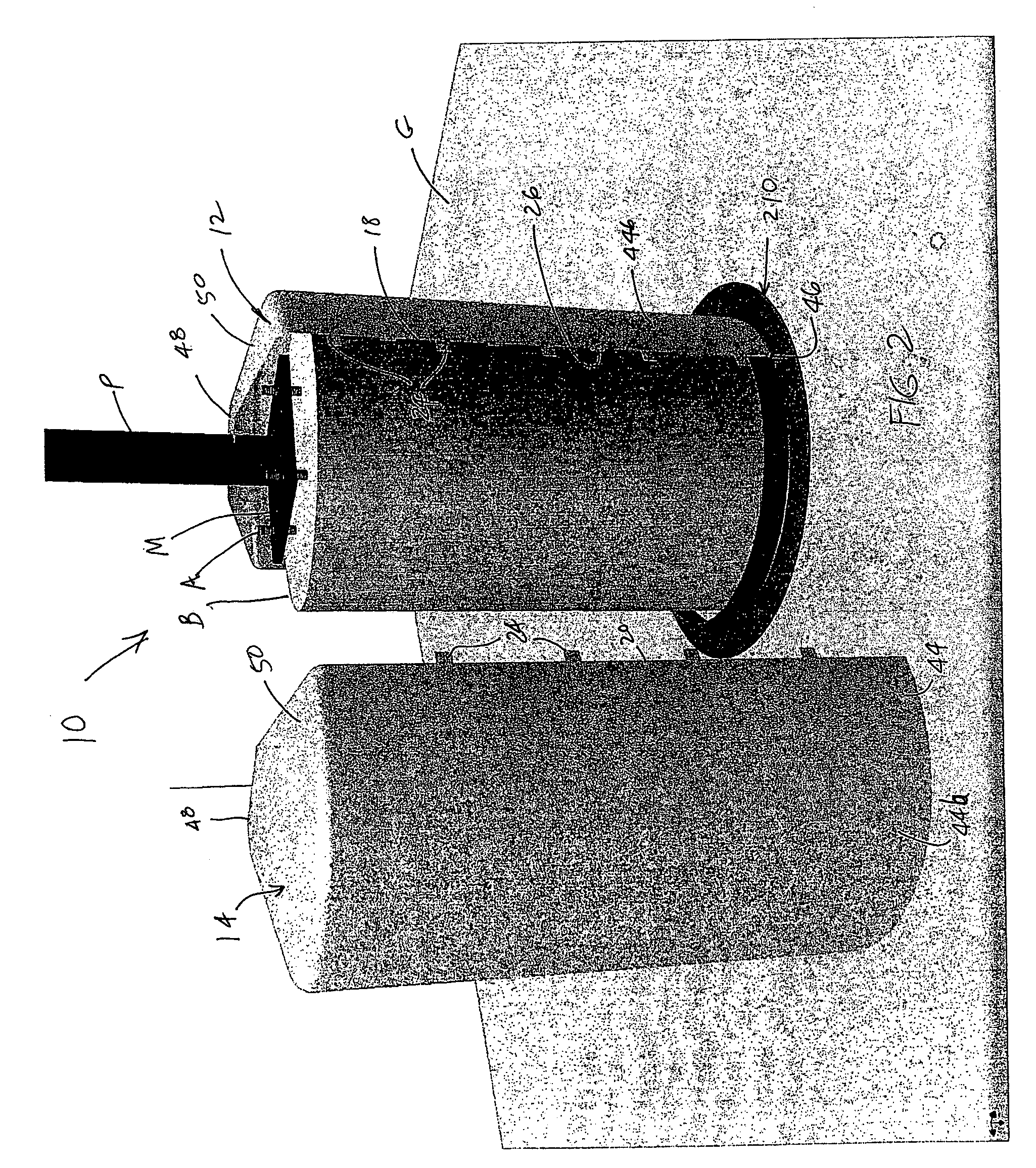
[0042]Referring to FIG. 1, the numeral 10 generally designates a cover of the present invention, which is particularly suitable for use on a pole assembly P, especially a lamp pole assembly, to cover the pole assembly's concrete base B and pole base plate M and optionally the concrete anchor bolts A that anchor the post to the base. As will be more fully described below, cover 10 will protect the concrete base from damage or corrosion due to sprinkler water, flying debris from lawn mowers, and will also cover defects or stains in the base.

[0043]In the illustrated embodiment, cover 10 includes a split housing construction with first and second cover halves 12 and 14, each having a substantially identical construction so that they may be molded or formed from the same mold. When mounted about pole assembly P and base B, cover 10 preferably covers the full length of the exposed portion of base B, which is typically cast in place and partially embedded in the ground G, so that cover 10 ...


PUM


Abstract

A cover for a concrete pole base of a pole assembly includes a cylinder-shaped wall and an upper wall at least partially closing the open upper end of the cylinder-shaped wall. The upper wall has an opening for receiving the post of the pole assembly, which is anchored to the ground by the concrete base. The cylinder-shaped wall has an inner diameter and a height sized to cover and enclose the concrete base. The upper wall has a plurality of nested regions of reduced wall thickness to form score lines to facilitate cutting the cover to increase adjust the height or the diameter of the opening to accommodate different pole assemblies.

Description

TECHNICAL FIELD AND BACKGROUND OF THE INVENTION[0001]The present invention generally relates to a cover for a concrete base, for example, a concrete pole base, and, more particularly, to a cover for a concrete lamp pole base.[0002]It is common practice to mount a pole, such as a lamp pole, on a concrete base, which is embedded or otherwise mounted to the ground. However, over time the appearance of these concrete bases tends to degrade from stains from either rust that accumulates at the pole mounting plate and / or the concrete anchor bolts that mount the pole to the concrete base or from iron deposits from sprinkler water distributed by sprinkler systems. In an effort to hide these unsightly stains, some concrete bases are painted. However, once painted, the bases have to be maintained and repainted periodically to maintain their aesthetic appearance.[0003]Consequently, there is a need for a method or device that can conceal concrete bases to hide these stains or other markings whic...

Claims


Application Information

Patent Timeline
IPC IPC(8): E04C3/30
CPCE04H12/2292
Inventor MCGLINCH, BRADLEY J.
Owner MCGLINCH BRADLEY J
Learn More