Pipeline protection system

a protection system and pipeline technology, applied in water supply installation, braking system, valve type, etc., can solve the problems of pipeline overpressure, pipeline is a major cost element of fluid extraction system, etc., and achieve the effect of improving the integrity of the system

Active Publication Date: 2008-01-03
BAKER HUGHES ENERGY TECH UK LTD
View PDF3 Cites 45 Cited by
  • Summary
  • Abstract
  • Description
  • Claims
  • Application Information

AI Technical Summary

Benefits of technology

[0007] It is an aim of the present invention to provide a HIPPS system which enables a controlled start-up and shutdown which improves the integrity of the system.

Problems solved by technology

Consequently, the pipeline is a major cost element of the fluid extraction system.
For a pipeline to withstand such pressure would require it to have a substantial wall thickness, and it is not cost effective to implement this for long pipelines.
However, a failure of the pressure reducing device may result in overpressure in the pipeline with disastrous results.
Thus loss of electrical or hydraulic power causes the valves 1 and 2 to close.
Although such known HIPPS systems are effective at protecting the pipeline, they are relatively basic, and do not address the problem of reducing the overpressure in the fluid system, which should be reduced before the HIPPS valves are re-opened and normal operation resumed.

Method used


Image

  • Pipeline protection system
  • Pipeline protection system
  • Pipeline protection system

Examples


Embodiment Construction

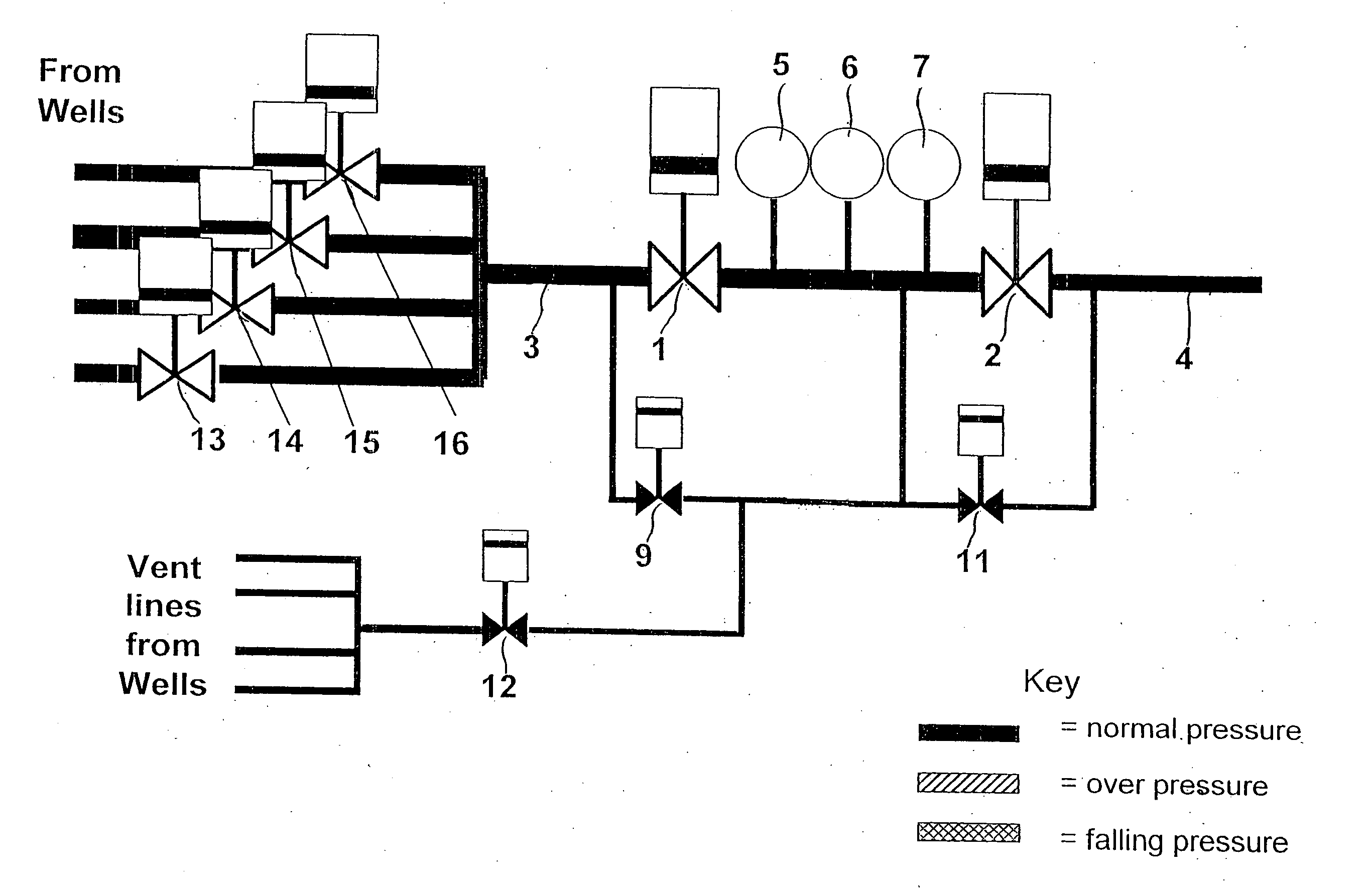
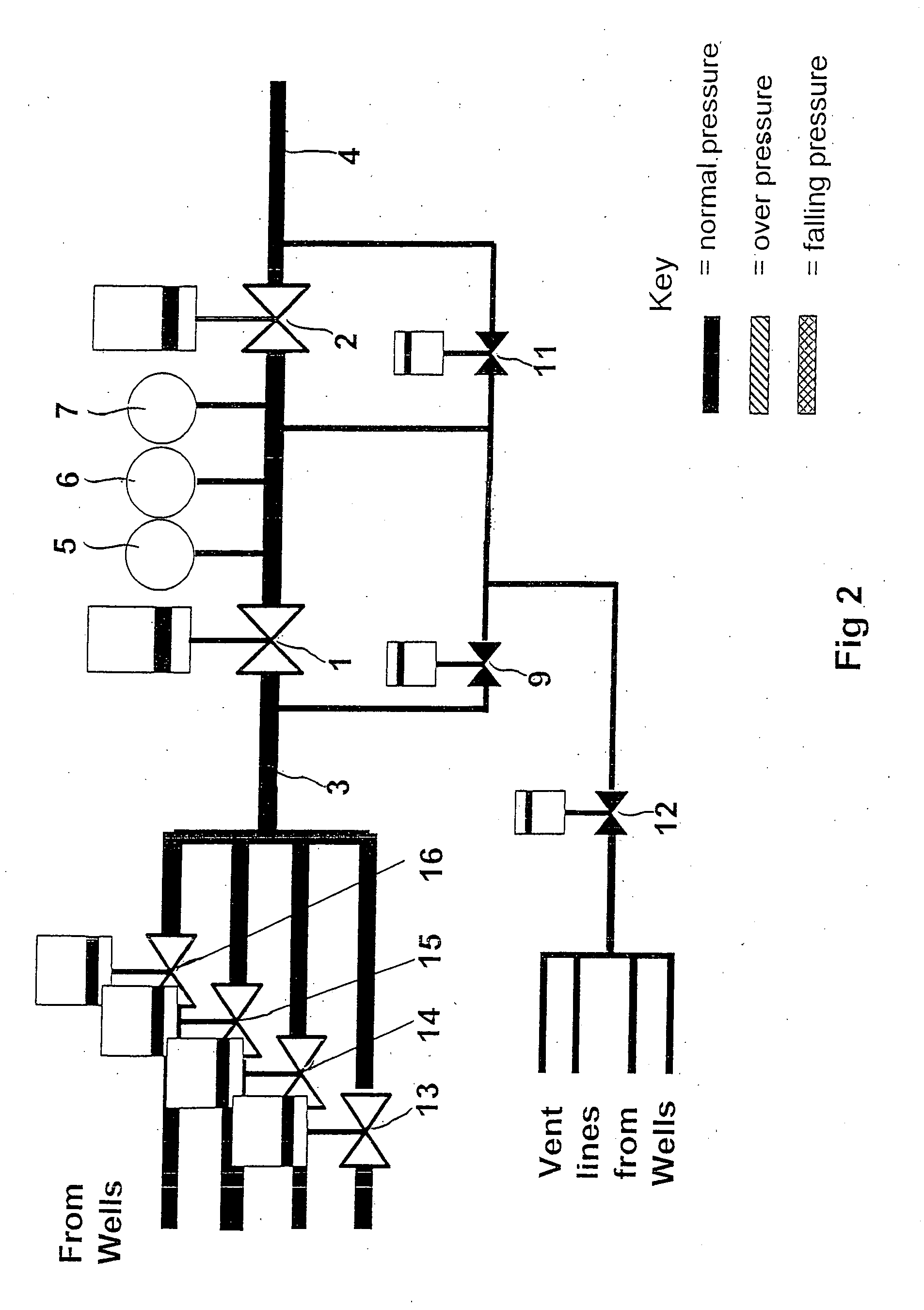
[0014]FIG. 2 shows an embodiment of the present invention in which the system is in normal, i.e. fault-free, operation. As shown, fluid enters the system from four wells connected via individual isolation valves 13, 14, 15, and 16 to a relatively thick-walled high pressure fluid extraction input flowline 3. This in turn connects to a relatively thin-walled lower pressure output pipeline 4. The fluid flow from flowline 3 to pipeline 4 is regulated by series-connected pipeline HIPPS barrier valves 1 and 2. Connected between pipeline HIPPS valves 1 and 2 are three pressure transducers 5, 6 and 7. A fluid bypass line is connected between flowline 3 and a location between valves 1 and 2, the bypass line including a by-pass valve 9. A further bypass branch is connected between the bypass line and pipeline 4, which includes a bypass valve 11. The bore of the bypass line and branch pipework is relatively small, typically having a diameter of about 2 inches (5.08 cm). This compares to a typi...


PUM


Abstract

A protection apparatus for detecting and reducing overpressure in a fluid pipeline having a fluid input end (3) and a fluid output end (4), the fluid input end being connected in use to a fluid source, comprises: first (1) and second (2) pipeline valves connected in series along the pipeline with the first pipeline valve being connected at a location closer to the input end than the connection location of the second pipeline valve, the first and second pipeline valves being independently switchable between open positions in which fluid flow through the pipeline is permitted and closed positions in which fluid flow through the pipeline is blocked; a pressure transducer for determining the fluid pressure in the pipeline at a point intermediate the first and second pipeline valves; a bypass line having a first end connected to the pipeline between the input end and the first pipeline valve and a second end connected to the pipeline between the first and second pipeline valves; a bypass valve (9) connected along the bypass line, said bypass valve being switchable between an open position in which fluid flow through the bypass line is permitted and a closed position in which fluid flow through the bypass line is blocked; a vent line connected to the bypass line between the bypass valve and the second end of the bypass line, the vent line leading to a venting means; and a vent valve (12) connected along the vent line, said vent valve being switchable between an open position in which fluid flow through the vent line is permitted and a closed position in which fluid flow through the vent line is blocked.

Description

CROSS-REFERENCE TO RELATED APPLICATION [0001] This application claims the benefit of United Kingdom Patent Application No. 0610069.7, filed on May 20, 2006, which hereby is incorporated by reference in its entirety. FIELD OF THE INVENTION [0002] This invention relates to a protection apparatus for detecting and reducing overpressure in a fluid pipeline and a method for resetting a pipeline protection system after tripping. BACKGROUND OF THE INVENTION [0003] Hydrocarbon wells, for example subsea oil wells, require a pipeline through which the hydrocarbon fluid is transported. In the case of subsea wells, these may be of substantial length, sometimes several tens of kilometres long. Consequently, the pipeline is a major cost element of the fluid extraction system. Many subsea wells have to contend with very high fluid pressures, for example as high as 700 bar. For a pipeline to withstand such pressure would require it to have a substantial wall thickness, and it is not cost effective ...

Claims


Application Information

Patent Timeline
Patent Type & Authority Applications(United States)
IPC IPC(8): F16K17/00
CPCF17D1/20F16K17/02Y10T137/7722Y10T137/7728Y10T137/8729Y10T137/87314Y10T137/87507Y10T137/87772Y10T137/87877F17D3/00F17D5/02
Inventor LAWRENCE EDWARDS, JEREMY PAUL
Owner BAKER HUGHES ENERGY TECH UK LTD
Why Eureka
Try Eureka