
Lighting fixture service access

a technology for lighting fixtures and access points, which is applied in the direction of fixed installation, lighting and heating equipment, lighting support devices, etc., can solve the problems of damage to recessed lighting fixtures, ceilings, etc., and achieve the effect of convenient servicing, improved service access, and convenient servicing

Active Publication Date: 2008-01-03
IDEAL IND LIGHTING LLC
View PDF7 Cites 58 Cited by
  • Summary
  • Abstract
  • Description
  • Claims
  • Application Information

AI Technical Summary

Benefits of technology

[0006]Another object of the invention is to provide a service access that facilitates servicing of components of a recessed lighting fixture from a position below the fixture.
[0007]Another object of the invention is to provide a service access that facilitates a servicing of a recessed lighting fixture installed in an otherwise inaccessible ceiling space, such as a space above a drywalled ceiling or the like.
[0008]Still another object of the invention is to provide an improved service access for a recessed lighting fixture installed in a location where access to lighting fixture components is otherwise difficult.
[0009]Yet another object of the invention is to provide an improved service access for a recessed lighting fixture where components are accessible without disassembly of the fixture.
[0010]Another object of the invention is to provide a modular lamp socketing assembly with improved heat dissipation.
[0011]Another object of the invention is to provide universality in configuring a basic fixture design for specific applications including varying of illumination, lamp type, socket type, reflector, heat dissipation properties, accessability of components, and of mechanical structure.

Problems solved by technology

However, a recessed lighting fixture may be inaccessible from above, such as when the fixture is part of a drywalled or similar ceiling, or when there is no easy access in a suspended ceiling.
Besides being time consuming, such servicing may cause damage to the recessed lighting fixture, the ceiling, and / or other adjacent structure or articles.

Method used


Image

  • Lighting fixture service access
  • Lighting fixture service access
  • Lighting fixture service access

Examples


Embodiment Construction

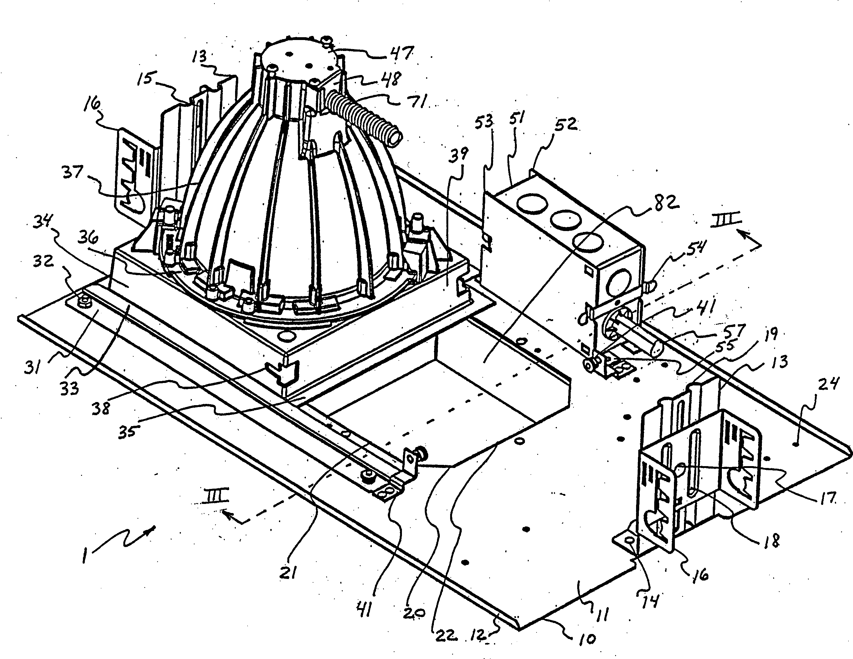
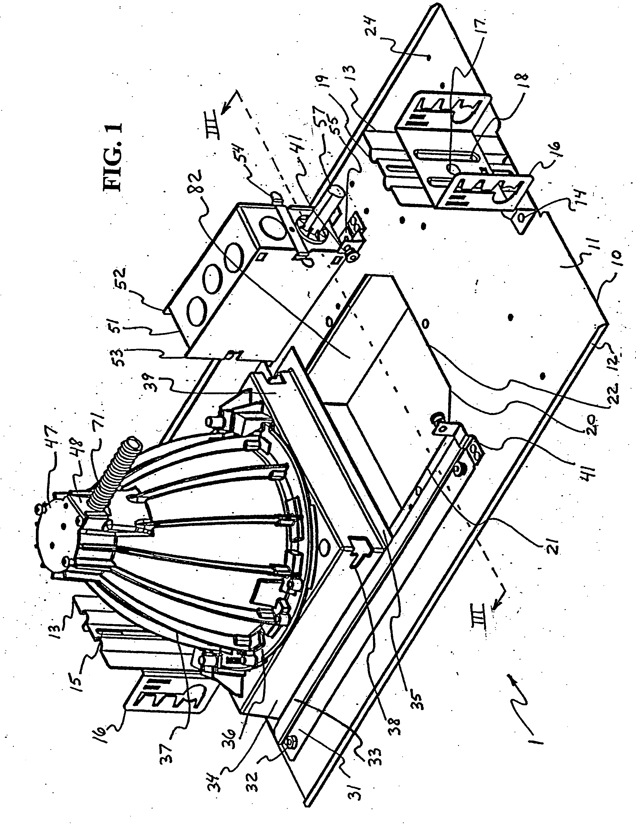
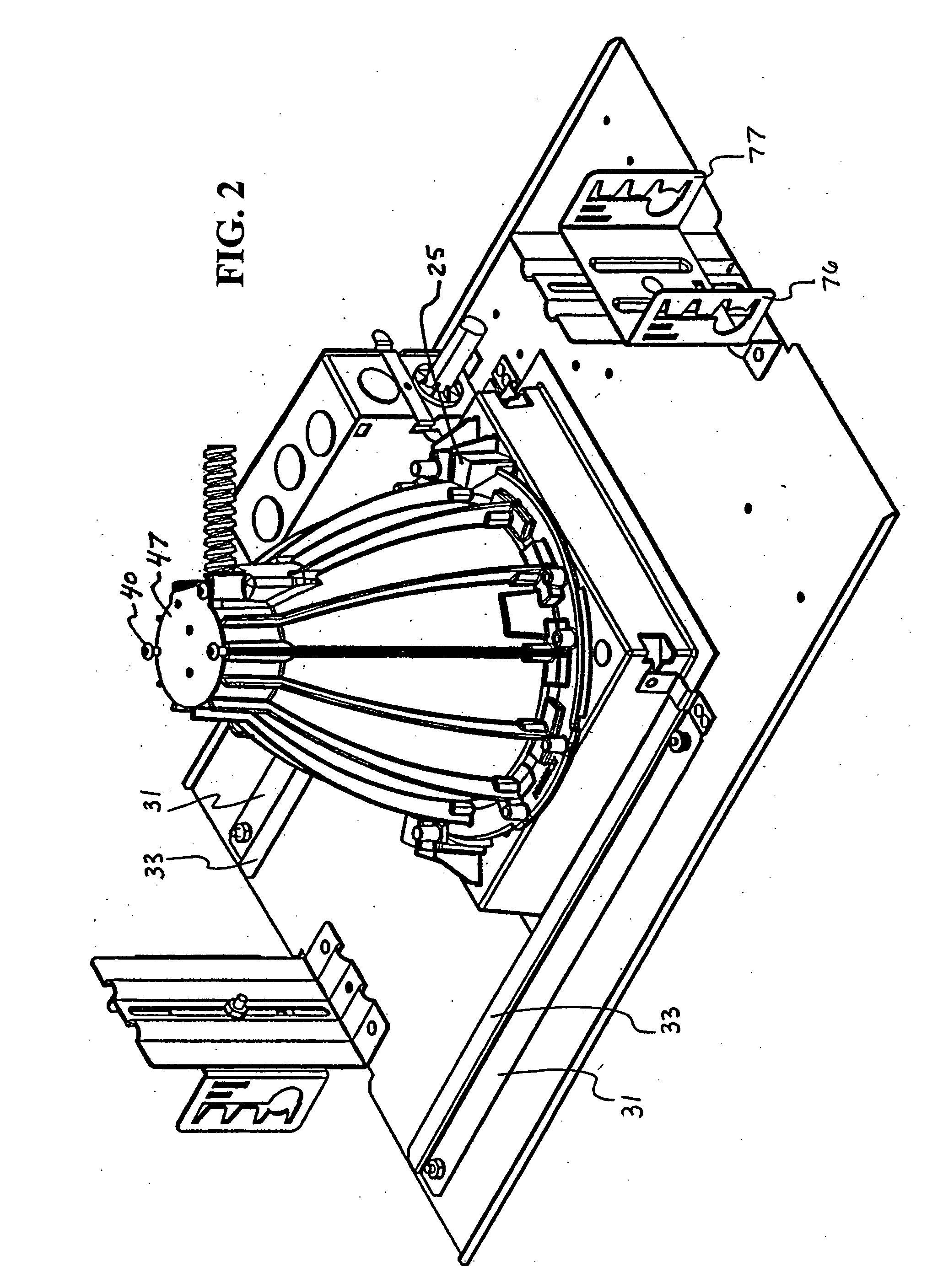
[0033]FIGS. 1 and 2 respectively show perspective views of a recessed lighting fixture 1 in a servicing / maintenance orientation and in a closed orientation. A flat type mounting plate 10 is formed of sheet metal and has a top surface 11. Bent edge portions 12 are formed along each longitudinal edge of plate 10. An L-shaped bracket holder 13 is attached on each lengthwise end of plate 10 using rivets 14 or other suitable fastener. Bracket holders 13 each have a vertical groove 15 formed in a center portion thereof. A mounting bracket 16 is slidably attached to each bracket holder 13 with a fastener 17, such as a bolt and lockwasher combination. Mounting bracket 16 and bracket holder 13 respectively have projections 18 and indentations 19 that align to assure that mounting bracket 16 remains in alignment with bracket holder 13 as a vertical position of mounting bracket 16 is vertically adjusted and then tightened in place with mounting ear adjustment nut / fastener 17. The just-describe...


PUM


Abstract

Apparatus includes a mounting plate having a hole in a center portion thereof, a recessed light support member having laterally-extending flanges on each of two essentially parallel sides, and a guide disposed on the top surface of the plate, the guide having a longitudinal section offset from the top surface by a distance greater than the thickness of the flanges, where the flanges of the recessed light support member are slidable laterally between the top surface of the plate and the longitudinal section of the guide. A method of servicing a lighting fixture having a can includes sliding the can laterally from a position where the can is centered over the hole to a position where a servicing space is effected between a perimeter of the hole and the can.

Description

FIELD OF THE INVENTION[0001]The invention relates to servicing of lighting fixtures and, more particularly, to a structure and method that improves maintainability by simplifying access to lighting fixture components.BACKGROUND OF THE INVENTION[0002]Many different shapes and applications exist for lighting fixtures, and fixtures of a general shape / application can have several different lamps with various power dissipations, voltages, photometrics, radiation patterns, etc. One or more different lamp types can be used in a single lighting fixture. Lighting fixture housings may be optimized for a given application by adapting the shape and / or location of reflectors, diffusers, baffles, louvers, shades, shields, and other components for achieving the desired illumination within electrical, heat, and other parameters for the particular installation.[0003]Lighting fixtures adapted to be recessed into a wall, such as by being disposed above a ceiling, are known. Such recessed lighting fixt...

Claims


Application Information

Patent Timeline
Patent Type & Authority Applications(United States)
IPC IPC(8): F21V19/00
CPCF21S8/02F21V19/04F21S8/026
Inventor MILETICH, DONKINNUNE, BRIAN L.
Owner IDEAL IND LIGHTING LLC
Learn More