Packet switch equipment and bandwidth control method using the same

a packet switch and bandwidth control technology, applied in data switching networks, digital transmission, electrical equipment, etc., can solve problems such as substantial impossible, failure of function, and inability to make a setup for every mac connectable to the second port in advan

Inactive Publication Date: 2008-01-03
SAMSUNG ELECTRONICS CO LTD
View PDF16 Cites 11 Cited by
  • Summary
  • Abstract
  • Description
  • Claims
  • Application Information

AI Technical Summary

Benefits of technology

[0013]Accordingly, the present invention has been made to solve the above-mentioned problems occurring in the prior art and provides additional advantages, by providing a packet switch equipment capable of allocating a bandwidth to a number of users dynamically , without the operator's intervention or according to default setups, when a bandwidth limitation function of a packet switch chip is utilized in a network switch equipment based on a packet switch chip, as well as a bandwidth control method using the same.

Problems solved by technology

However, this function fails if a number of users are connected to a single port.
However, when the conventional packet switch chip 12 is used to limit the bandwidth with regard to a number of users, the following problems occur.
This is substantially impossible.
In other words, when the amount of bandwidth used by specific source MAC is limited, based on the source MAC, with regard to packets flowing into the port, no setup regarding every MAC connectable to the second port can be made in advance.
Second, even when users connectable to a port have been determined in advance, the operator must manually set up information regarding the users onto the chip.
Third, even when the number of users connectable to a port is limited and setups regarding them can be made, some portions of the bandwidth may not be used although they are available.
This is a waste of bandwidth.

Method used


Image

  • Packet switch equipment and bandwidth control method using the same
  • Packet switch equipment and bandwidth control method using the same
  • Packet switch equipment and bandwidth control method using the same

Examples


Embodiment Construction

[0020]Hereinafter, an embodiment of the present invention will be described with reference to the accompanying drawings. For the purposes of clarity and simplicity, a detailed description of known functions and configurations incorporated herein is omitted to avoid making the subject matter of the present invention unclear.

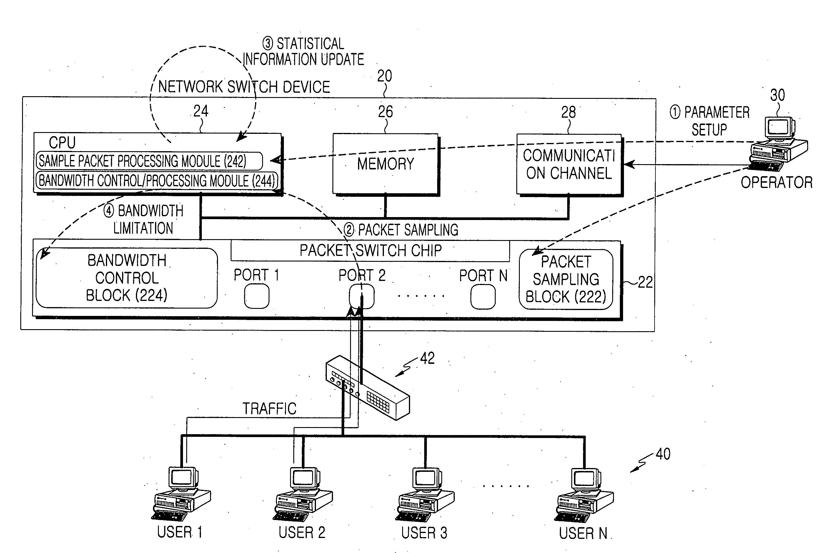
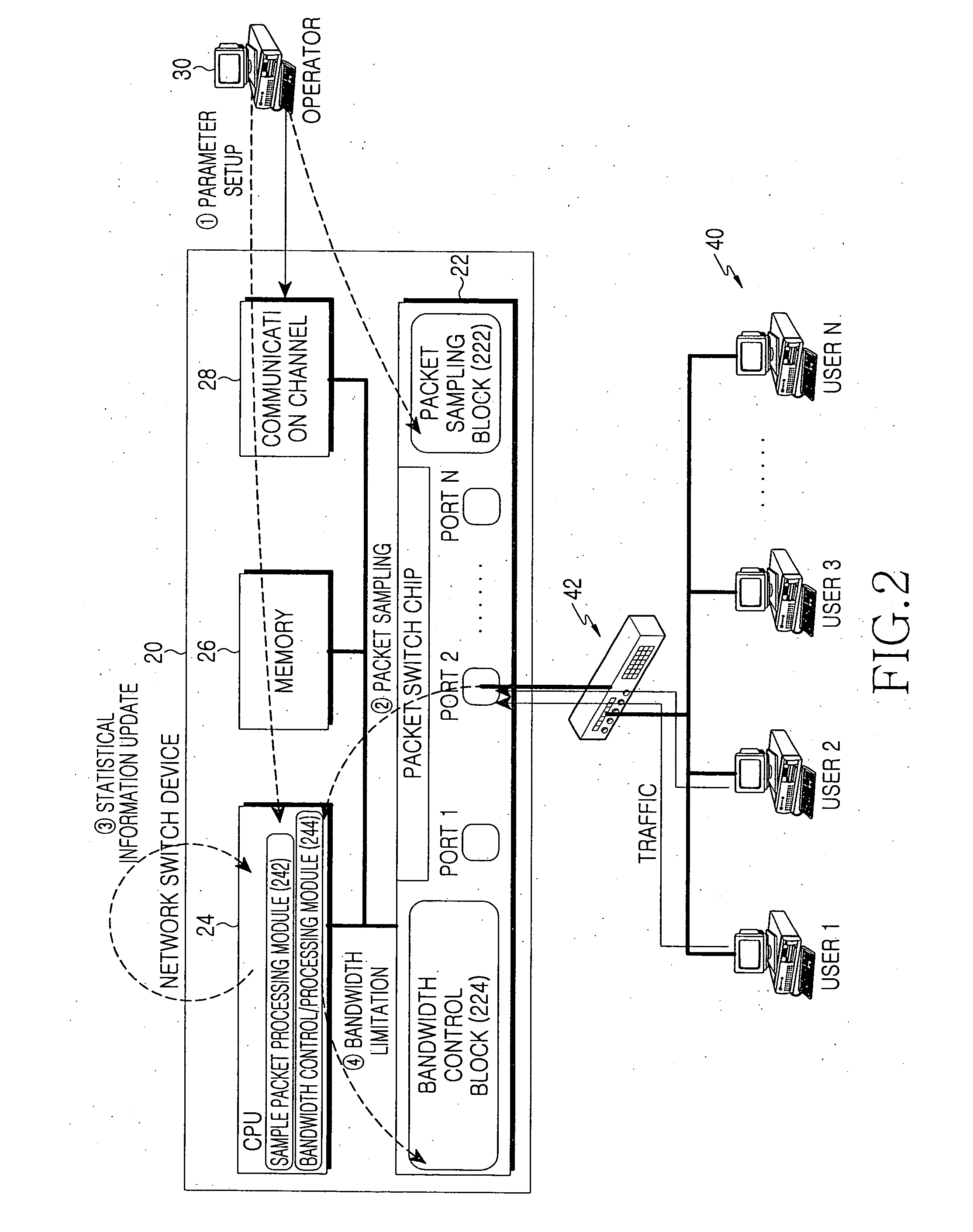
[0021]FIG. 2 is a block diagram showing the construction of a packet switch equipment according to an embodiment of the present invention. Referring to FIG. 2, the packet switch equipment 20 includes a packet switch chip 22 having a number of ports labeled PORT 1 to PORT N, a memory 20 for storing information regarding control of packets and ports via the packet switch chip 22, a communication channel 28 for communicating with an operator terminal 30 to receive setup(s) information and parameters necessary for operation of the equipment, and a CPU 24 for controlling the overall switching operation of the Ethernet switch equipment 20 including the packet switch chi...


PUM


Abstract

Disclosed is a packet switch equipment and a band control method using same. In accordance with one embodiment of the invention, a number of packets are sampled by using a packet sampling function provided by a packet switch chip, and the sampled packets are transmitted to a CPU. By using the transmitted sample packets, the total amount of bandwidth used by a corresponding user is estimated based on the source MAC address or the source IP address. If the estimated value exceeds a predetermined threshold, a bandwidth limitation function is applied to the user that is providing packets that exceed the bandwidth. A number of users can be dynamically recognized even when they are undefined, and a dynamic bandwidth limitation function is performed by tracking the bandwidth used by a corresponding user.

Description

CLAIM OF PRIORITY[0001]This application claims the benefit of the earlier filing date, pursuant to 35 USC 119, to that patent application entitled “Packet Switch Equipment and Bandwidth Control Method Using the Same” filed with the Korean Intellectual Property Office on Jun. 30, 2006 and assigned Serial No. 2006-61099, the contents of which are incorporated herein by reference.BACKGROUND OF THE INVENTION[0002]1. Field of the Invention[0003]The present invention relates to packet-based networks (e.g. Ethernet), and more particularly to a packet switch equipment based on a packet switch chip and a bandwidth control method using the same.[0004]2. Description of the Related Art[0005]Network switch devices based on a packet switch chip provide a port-based bandwidth limitation function by using functionalities provided by their own chip. The bandwidth limitation function provided by the packet switch chip enable users to set up a series control conditions regarding bandwidth limitation o...

Claims


Application Information

Patent Timeline
Patent Type & Authority Applications(United States)
IPC IPC(8): H04L12/56
CPCH04L47/20H04L47/10H04L47/76
Inventor JOO, MIN-KYUKIM, HOON-JAEPARK, HAN-SEUNGKIM, SEONG-HA
Owner SAMSUNG ELECTRONICS CO LTD
Why Eureka
Try Eureka