Extending IP/MPLS services reachability over ATM backbone networks

a backbone network and ip/mpls technology, applied in the field of communication networks, to achieve the effect of reducing costs

Inactive Publication Date: 2008-01-03
SOUND VIEW INNOVATIONS
View PDF6 Cites 95 Cited by
  • Summary
  • Abstract
  • Description
  • Claims
  • Application Information

AI Technical Summary

Benefits of technology

[0010]Advantageously, the invention allows service providers to extend MPLS based services (any type of service that rides over an LSP, e.g. VPLS, IP VPNs, pseudo wires, etc.) over an ATM backbone to locations or regions where using the ATM backbone makes more sense. New services can now reach locations where the ATM backbone is more prevalent or where newer technologies such as Ethernet over POS, are more slowly being introduced (e.g. Eastern Europe, Middle East, Africa, Russia, China).
[0011]Another advantage of the LSP transport capability of the invention is that it enables the provision of a new type of service offering to customers, namely an LSP L2 service. For example, carriers looking for adding services that can be carried over an existing ATM/multi-service backbone could benefit by offering “LSP trunking” services. A service provider can now assign a particular LSP with specific service categories and bandwidth requirements to an SPVC that matches those service categories for transport, and another LSP with different characteristics to another SPVC. This LSPs to multiple SPVC mappings are not currently available.
[0012]Also, this solution does not require more costly ATM cards on PE or P routers of the MPLS network, as per the existing solutions. Rather, less expensive Ethernet or POS can be used from the MPLS edge to the ATM network, from the same multi-service switches that already exist in the ATM network. The lower costs are also due to the fact t...

Problems solved by technology

There are some markets and regions in the world where there exi...

Method used


Image

  • Extending IP/MPLS services reachability over ATM backbone networks
  • Extending IP/MPLS services reachability over ATM backbone networks
  • Extending IP/MPLS services reachability over ATM backbone networks

Examples


Embodiment Construction

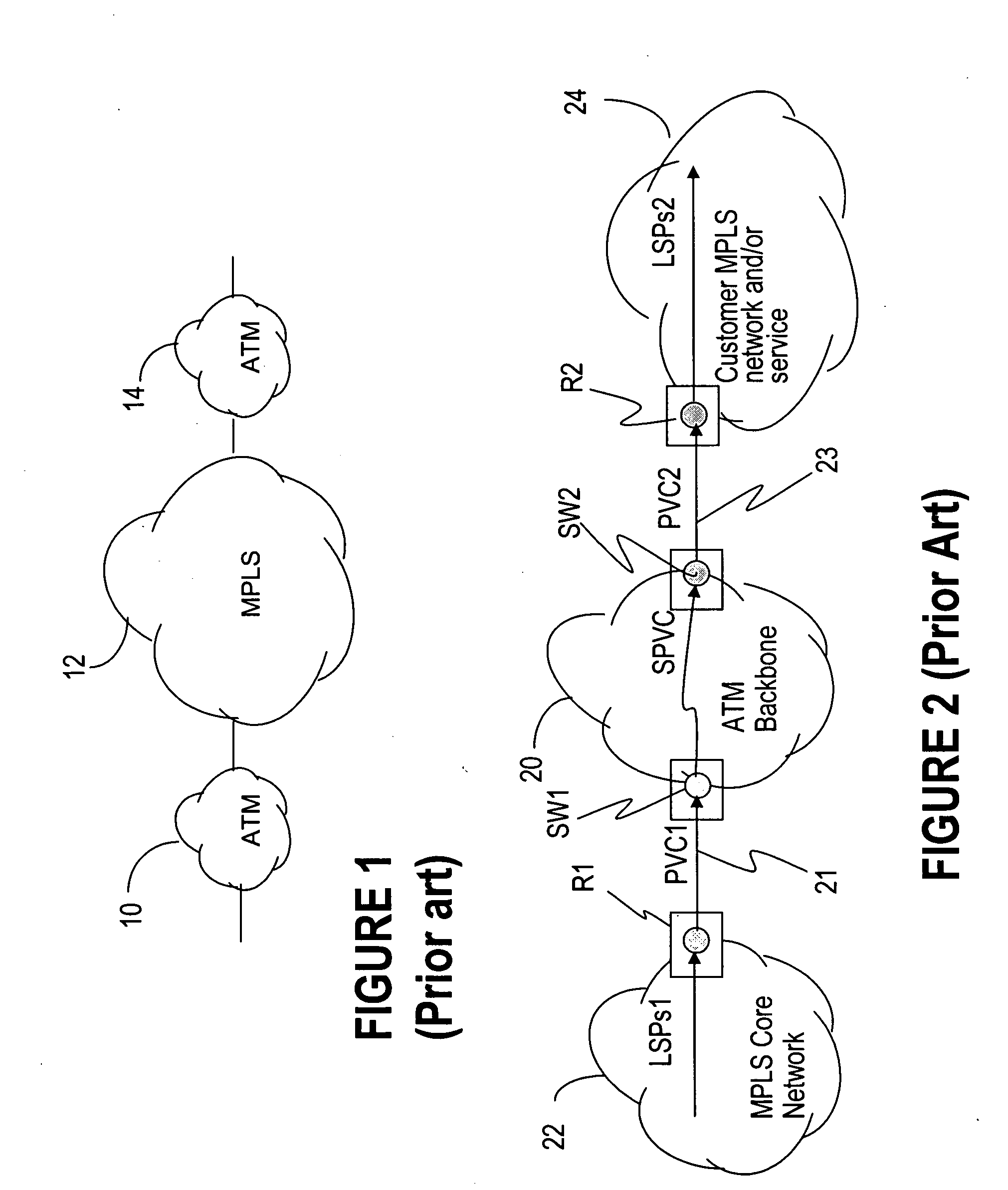
[0022]FIG. 1 shows a typical ATM / MPLS interworking application well understood by the industry, in which two ATM networks 10 and 14 are interconnected via an MPLS network 12. A brief description of the types of networks under consideration and the most relevant terms needed for understanding the invention are presented next.

[0023]ATM is a cell switching and multiplexing technology that combines the benefits of circuit switching (guaranteed capacity and constant transmission delays) with those of packet switching (flexibility and efficiency for Internet traffic). An ATM network, such as network 10 of FIG. 1, includes ATM switches and ATM endpoints. An ATM switch reads and updates the cell header information and quickly switches it from the input interface to the output interface towards a destination. An ATM endpoint includes ATM network interface adapters. A virtual channel (VC) is a concept used to describe uni / bidirectional transport of ATM cells associated by a common unique iden...


PUM


Abstract

The invention enables an LSP or embedded LSPs to be mapped directly to an SPVC and carried over the ATM network. A unidirectional SPVC is established by associating it to a particular ingress LSP at the SPVC source endpoint on a multi-service switch, and to an egress LSP on the SPVC destination endpoint on another multi-service switch. The information necessary to establish the SPVC is appended in the SPVC setup message and includes LSP specific information such as the far end router ID and LSP label information, be it transport label or the full label stack. The information in the modified setup message is then used by the destination endpoint to find and connect the SPVC to the correct LSP. Incoming traffic from the LSP is switched to the SPVC at the source endpoint. The SPVC carries this traffic through the ATM network, and then the traffic is switched to the egress LSP when it emerges from the ATM network at the destination endpoint.

Description

FIELD OF THE INVENTION[0001]The invention is directed to communication networks and in particular to extending IP / MPLS service reachability over ATM backbone networks.BACKGROUND OF THE INVENTION[0002]The telecommunication industry today is almost entirely focused on transporting ATM services over an MPLS core. However, there is interest from current ATM backbone service providers to make use of that backbone to provide enhanced services such as additional IP / MPLS services. In addition, the total footprint of ATM backbone networks today is much larger than MPLS based networks (node counts, etc.), since MPLS networks are relatively in a development stage. There are some markets and regions in the world where there exists ATM footprint and transport, but not yet full IP / MPLS or Ethernet. Therefore, it could be convenient to transport some IP / MPLS based services over existing ATM backbones instead of installing new equipment at all sites.[0003]There is a need to extend the reach of IP / M...

Claims


Application Information

Patent Timeline
IPC IPC(8): H04L12/56
CPCH04L12/5601H04L47/10H04L45/50H04L45/00H04L47/43
Inventor RAJSIC, CARL
Owner SOUND VIEW INNOVATIONS
Why Eureka
Try Eureka