Synchronous memory read data capture

a technology of read data and synchronous memory, applied in the field of synchronous memories, can solve the problems of requiring higher level intelligence somewhere in the controller, unable to solve fixed timing robustly, and unable to adjust for timing drift during operation, etc., and achieves the effect of low latency clock domain crossing and simple operation

Active Publication Date: 2008-01-03
MOSAID TECH
View PDF8 Cites 53 Cited by
  • Summary
  • Abstract
  • Description
  • Claims
  • Application Information

AI Technical Summary

Benefits of technology

[0024]Another embodiment of the invention is a simple, low latency clock domain crossing circuit based on the DQS latched sample of the counter.

Problems solved by technology

A first problem associated with this alignment of read command and data is to determine, on system initialization, where in time to position the read data DQS enable signal so that it falls within the 2 bit preamble.
A second problem is how to adjust for timing drift during operation caused by temperature or supply voltage drift.
A third problem is how to transfer data clocked in with DQS to the system clock domain when the phase between the DQS clock and master system clock CLK can be completely arbitrary.
Fixed timing is not a robust solution.
A disadvantage of this approach is that it requires higher level intelligence somewhere in the controller, and a significant amount of time during system initialization to determine the optimum setting.
Also, it cannot accommodate timing drift during operation.
The disadvantage of this approach is that it requires 2 additional pins, PCB traces, and consumes power.
It does not perfectly match the actual command to read data loop-around delay.

Method used


Image

  • Synchronous memory read data capture
  • Synchronous memory read data capture
  • Synchronous memory read data capture

Examples


Embodiment Construction

[0038]In the following detailed description of sample embodiments of the invention, reference is made to the accompanying drawings which form a part hereof, and in which is shown by way of illustration specific sample embodiments in which the present invention may be practiced. These embodiments are described in sufficient detail to enable those skilled in the art to practice the present invention, and it is to be understood that other embodiments may be utilized and that logical, mechanical, electrical, and other changes may be made without departing from the scope of the present invention. The following detailed description is, therefore, not to be taken in a limiting sense, and the scope of the present invention is defined by the appended claims.

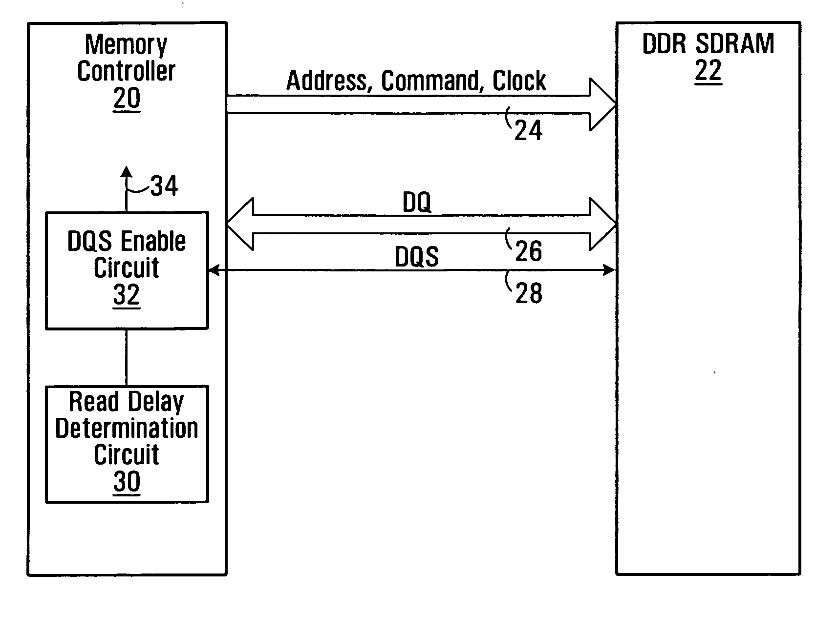
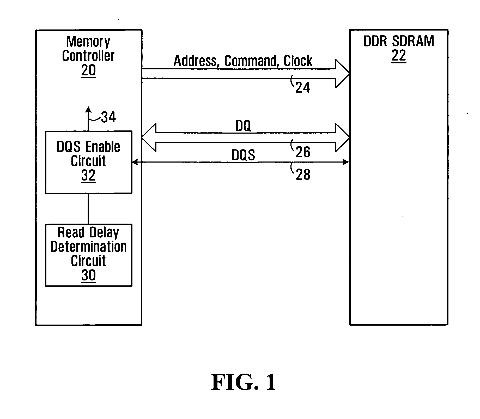
[0039]Referring now to FIG. 1, shown is a memory controller 20 connected to a DDR-SDRAM 22 through connections including: a unidirectional bus 24 used to send addresses, commands and clock from the memory controller 20 to the DDR SDRAM 22...


PUM


Abstract

A method of snap-shot data training to determine the optimum timing of the DQS enable signal in a single read operation is provided. This is accomplished by first writing a Gray code count sequence into the memory and then reading it back in a single burst. The controller samples the read burst at a fixed interval from the time the command was issued to determine the loop-around delay. A simple truth table lookup determines the optimum DQS enable timing for normal reads. Advantageously, during normal read operations, the first positive edge of the enabled DQS signal is used to sample a counter that is enabled every time a command is issued. If the counter sample changes, indicating timing drift has occurred, the DQS enable signal can be adjusted to compensate for the drift and maintain a position centered in the DQS preamble. This technique can also be applied to a system that uses the iterative approach to determining DQS enable timing on power up. Another embodiment of the invention is a simple, low latency clock domain crossing circuit based on the DQS latched sample of the counter.

Description

FIELD OF THE INVENTION[0001]The present invention relates generally to synchronous memories and associated memory controllers. More particularly, the present invention relates to the control and transfer of read and write data between a memory controller and a synchronous memory using bidirectional databusses and bidirectional data strobe signals.BACKGROUND OF THE INVENTION[0002]In source synchronous signaling, a data strobe clock is driven by the transmitting device along with the data. The clock and data paths from transmitter to receiver are matched. At the receiving device the data strobe clock is used to latch incoming data. In Double Data Rate (DDR) SDRAM memory systems, the external databuses are bidirectional. Write data is sent to the memory from a memory controller and read data is sent from the memory to the controller. When no data is being sent, the bus returns to a tri-state level defined by the bus transmission line termination voltage.[0003]Control of the bidirection...

Claims


Application Information

Patent Timeline
Patent Type & Authority Applications(United States)
IPC IPC(8): G06F13/00
CPCG06F13/4243G11C2207/2254G11C29/50012G11C7/1066G11C11/409G11C11/407G11C11/4076
Inventor GILLINGHAM, PETERMCKENZIE, ROBERT
Owner MOSAID TECH
Why Eureka
Try Eureka