Eureka AIR delivers breakthrough ideas for toughest innovation challenges, trusted by R&D personnel around the world.

Tow Catch For Fiber Placement Head

Inactive Publication Date: 2008-01-10
INGERSOLL MACHINE TOOLS
View PDF8 Cites 69 Cited by
  • Summary
  • Abstract
  • Description
  • Claims
  • Application Information

AI Technical Summary

Benefits of technology

[0013]The arm of a tow catch, according to the invention, may also include a manual release lever, extending from the arm and adapted for application of a force thereto for pivoting the arm in a forward direction about the pivot point, to thereby lift the distal end of the arm away from the support.

Problems solved by technology

In the event that the pinch cylinder or tow clamping mechanism should fail, however, or a tow should break between the pinch cylinder and the creel, the tension on the tow will tend to draw the tow back toward the creel.
This is an undesirable occurrence, because rethreading the tow through all of the redirects and feeding it back to the fiber placement head can be a complex and time-consuming process, during which the automated fiber placement operation must be shut down.

Method used


Image

  • Tow Catch For Fiber Placement Head
  • Tow Catch For Fiber Placement Head
  • Tow Catch For Fiber Placement Head

Examples


Embodiment Construction

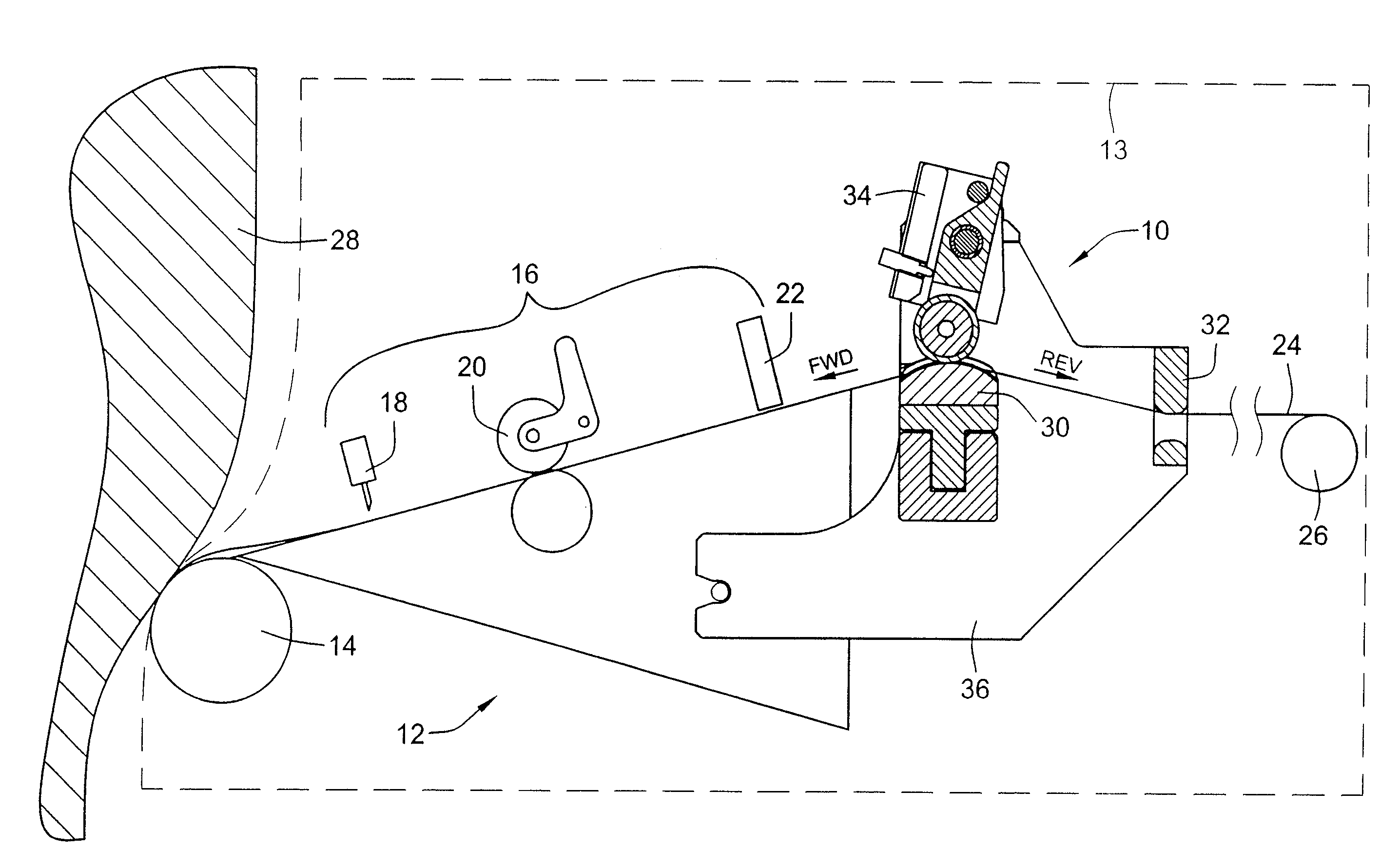
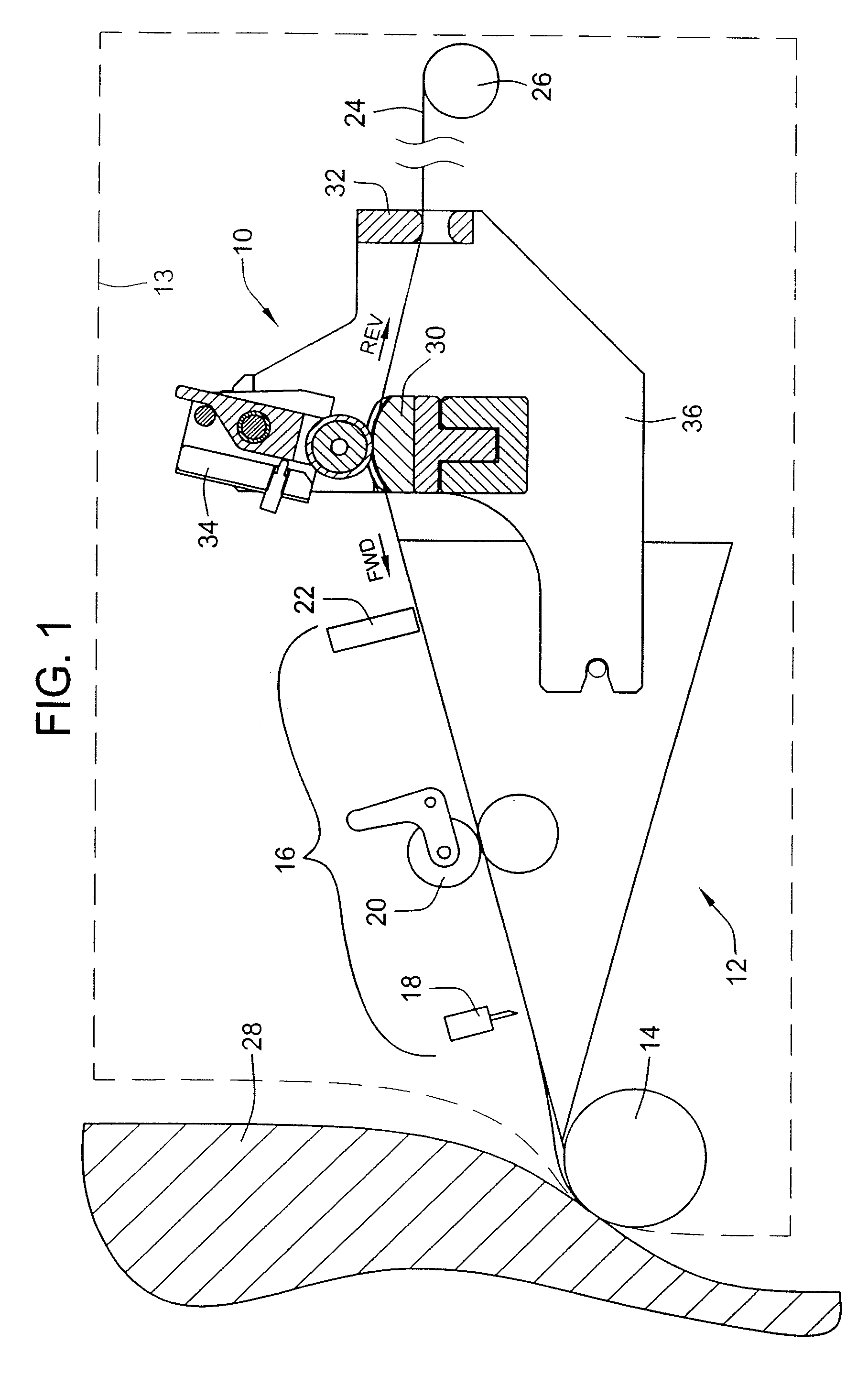
[0031]FIG. 1 shows a first exemplary embodiment of a tow catch apparatus 10, according to the invention, attached to a fiber placement head 12, of an automated fiber placement machine 13. The fiber placement head 12 includes a compaction roller 14, and a cut / add mechanism 16, with the cut / add mechanism 16 including a tow cutter 18, feed roller mechanism 20, and a tow clamp mechanism 22.

[0032]As illustrated in FIG. 1, each individual tow 24, is fed from a separate reel 26 of fiber material, located within a creel (not shown) of the fiber placement machine 13. The creel also includes a reel tensioner (not shown) operatively attached to the reel 26 for applying a tensile force to the tow 24.

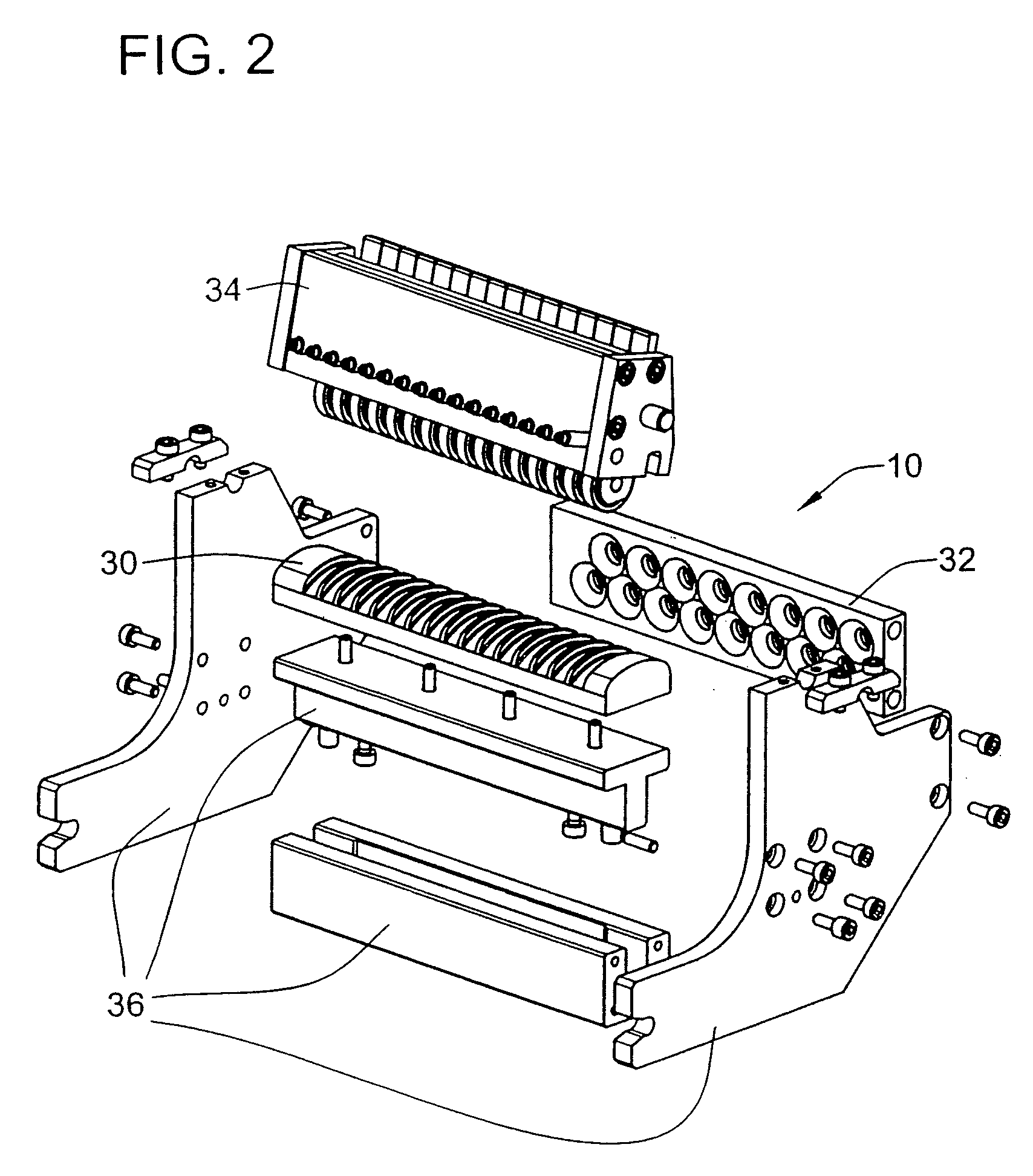
[0033]From the reel 26, the tow 24 is fed through the tow catch apparatus 10 attached to the head 12, to be pressed into place on the surface of a tool 28 by the compaction roller 14. From FIG. 1, it will be noted that the tow catch apparatus 10 is disposed between the tow clamp mechanism 22 and the...


PUM

PropertyMeasurementUnit
distanceaaaaaaaaaa
spring forceaaaaaaaaaa
forceaaaaaaaaaa

Abstract

An apparatus and method are provided, for selectively clamping a fiber tow against a support in a fiber placement head, in a manner allowing one-way motion of the tow in a forward direction from an input side to an output side of the support, and precluding motion of the tow in a reverse direction from the output side to the input side of the support, through use of a tow catch apparatus mounted on the fiber placement head, at a position along the forward path of the tow before the shears and clamps of a cut / add mechanism.

Description

CROSS-REFERENCE TO RELATED PATENT APPLICATIONS[0001]This patent application claims the benefit of U.S. Provisional Patent Application No. 60 / 819,677, filed Jul. 10, 2006, the disclosure and teachings of which are incorporated herein in their entireties, by reference.FIELD OF THE INVENTION[0002]This invention relates to automated fiber placement machines, and more particularly to a method and apparatus for precluding withdrawal of a fiber tow away from a fiber placement head, in the event of breakage of the tow and / or failure of a tow clamping mechanism to hold the tow in place after the tow is cut during a cut / add operation.BACKGROUND OF THE INVENTION[0003]During automated fiber placement, a number of tows, or tapes, of fiber are typically fed in parallel fashion, as a band of tows, through a fiber placement head to a compaction roller which places the tows onto the surface of a tool. Each individual tow or tape is supplied from a spool, which is typically located in a stationary cr...

Claims


Application Information

Patent Timeline
Patent Type & Authority Applications(United States)
IPC IPC(8): D01H13/00
CPCB29C70/384Y10T156/1343B29C70/545
Inventor RINDELS, CHRIS
Owner INGERSOLL MACHINE TOOLS
Why Eureka
Eureka Blog
Learn More