Micro electro mechanical system device

a mechanical system and micro-electromagnetic technology, applied in the direction of magnets, magnets, instruments, etc., can solve the problems of reducing the driving efficiency of the mems device, reducing the strength of the magnetic field, and the magnetic field should travel a relatively long distance, so as to prevent the deformation of the stage. , the effect of precise scanning

Inactive Publication Date: 2008-01-10
SAMSUNG ELECTRO MECHANICS CO LTD
View PDF3 Cites 9 Cited by
  • Summary
  • Abstract
  • Description
  • Claims
  • Application Information

AI Technical Summary

Benefits of technology

[0009] The present invention provides an MEMS device that performs precise scanning by structurally preventing deformation of a stage having a light reflecting surface.
[0013] When the stage is in a horizontal position, the fixed combs and the driving combs may face each other at the same height and overlap each other to a maximum level, and when the stage and the driving combs are rotated, an overlapping area between the fixed combs and the driving combs may decrease.

Problems solved by technology

Since the driving coil is wound around the light reflecting surface of the stage, the size and inertia mass of the driving coil increase, thereby decreasing the driving efficiency of the MEMS device.
Furthermore, since the driving coil is wound around a relatively large area, the magnetic field should travel a relatively long distance.
This lowers the strength of the magnetic field and causes a driving power loss.
However, in this case, the light reflecting surface directly receives heat generated from the lower driving coil and thus undergoes thermal deformation.

Method used


Image

  • Micro electro mechanical system device
  • Micro electro mechanical system device
  • Micro electro mechanical system device

Examples


Embodiment Construction

[0039] An MEMS device will now be described more fully with reference to the accompanying drawings, in which exemplary embodiments of the invention are shown.

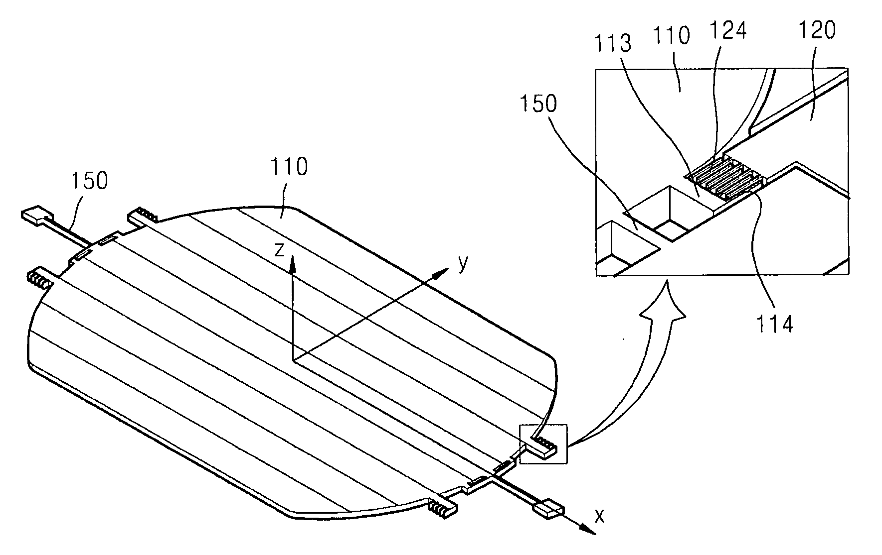
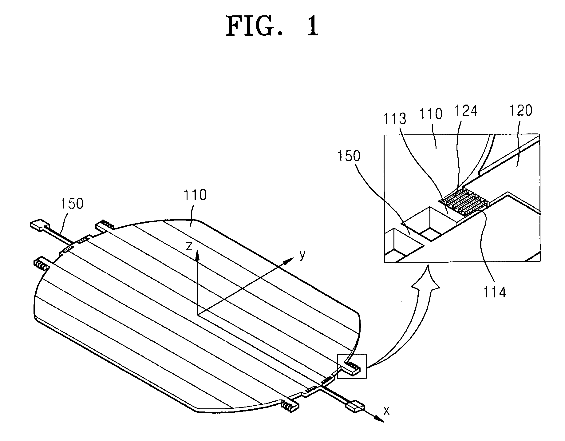
[0040]FIG. 1 is a perspective view illustrating main parts of an MEMS device according to an exemplary embodiment of the present invention. The MEMS device includes a stage 110 operating in vibration mode, an axle 150 supporting the stage 110 and functioning as a rotating center of the stage 110, and an outer frame 120 (illustrated only in the enlarged view of FIG. 1 for clarity) surrounding the stage 110. The MEMS device further includes a capacitive sensor detecting the rotation of the stage 110.

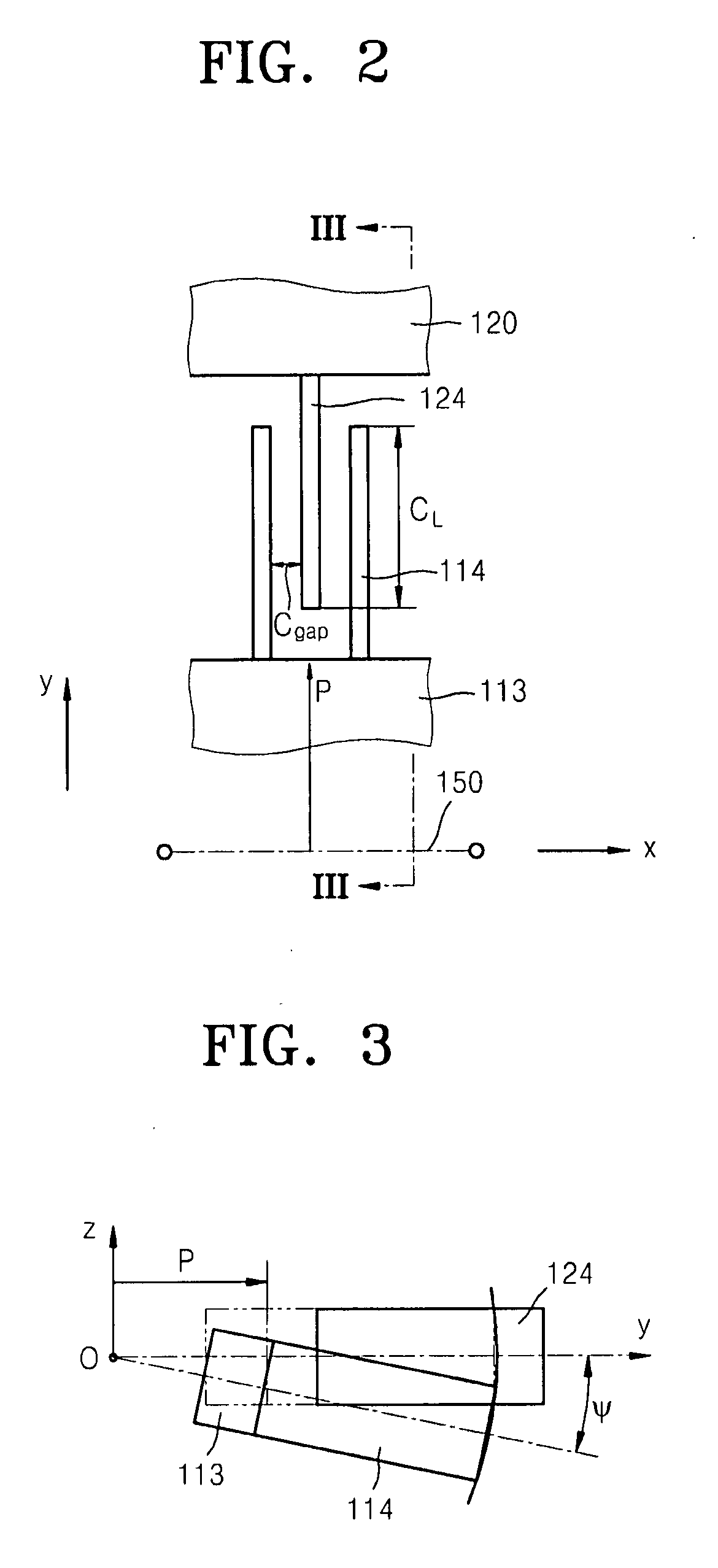
[0041] The capacitive sensor includes a sensing arm 113 extending from an end of the stage 110 at a predetermined distance from the axle 150 in parallel with the axle 150 (in an x-axis direction), a plurality of driving combs 114 evenly extending from the sensing arm 113 in an y-axis direction perpendicular to the axle 150, and a pl...


PUM

PropertyMeasurementUnit
distanceaaaaaaaaaa
capacitanceaaaaaaaaaa
magnetic fieldaaaaaaaaaa

Abstract

A micro electro mechanical system (MEMS) device is provided. The MEMS device includes: a stage which operates in a vibration mode; an axle which supports the stage and allows rotation of the stage; and a capacitive sensor which detects rotation of the stage. The capacitive sensor includes: a sensing arm which extends from the stage; driving combs which extend from the sensing arm and rotated together with the stage; fixed combs which are fixedly supported for engagement with the driving combs, the fixed combs including surfaces overlapping opposite surfaces of the driving combs in accordance with the rotation of the driving combs; and a capacitance sensing portion which detects a capacitance change of the driving combs and the fixed combs. Therefore, the MEMS device performs precise scanning by structurally preventing deformation of the stage having a light reflecting surface.

Description

CROSS-REFERENCE TO RELATED PATENT APPLICATIONS [0001] This application claims priority from Korean Patent Application No. 10-2006-0053551, filed on Jun. 14, 2006, in the Korean Intellectual Property Office, the disclosure of which is incorporated herein in its entirety by reference. BACKGROUND OF THE INVENTION [0002] 1. Field of the Invention [0003] Apparatuses consistent with the present invention relate to a micro electro mechanical system (MEMS) device, and more particularly, to an MEMS device that performs precise scanning by structurally preventing deformation of a stage having a light reflecting surface and includes a precise sensing structure for detecting the rotation speed and direction of the stage. [0004] 2. Description of the Related Art [0005] MEMS devices are frequently used in display devices, laser printers, precise measuring instruments, precise machining devices, etc. For example, in a display device, an MEMS device is used as an optical scanner for reflecting or d...

Claims


Application Information

Patent Timeline
Patent Type & Authority Applications(United States)
IPC IPC(8): H01F7/08G01R27/26
CPCG02B26/085H01F2007/068H01F7/066B81B7/00B81B7/02G02B26/00G02B26/08
Inventor JEONG, HEE-MOONKANG, SEOK-JINCHO, JIN-WOOKO, YOUNG-CHULJEONG, HYUN-KU
Owner SAMSUNG ELECTRO MECHANICS CO LTD
Why Eureka
Try Eureka