Brillouin optical time domain analysis meter capable of locking frequencies of two lasers based on optical phase-locked loop

An optical time domain analyzer and laser technology, applied in the direction of using optical devices to transmit sensing components, etc., can solve the problems of high price, slow frequency scanning speed, complex structure, etc., and achieve the effect of simple structure, simplified system, and reduced cost.

Active Publication Date: 2012-12-19
HARBIN INST OF TECH
View PDF5 Cites 14 Cited by
  • Summary
  • Abstract
  • Description
  • Claims
  • Application Information

AI Technical Summary

Problems solved by technology

[0005] The purpose of the present invention is to solve the problem of high price, complex structure and large volume of the existing device using a microwave frequency counter to detect the beat frequency signal after the frequency mixing of two lasers. The problem of slow frequency scanning speed and narrow frequency scanning range caused by the slow response speed of the optical delay line generated by the frequency locking and scanning between semiconductor lasers, provides a bridging system based on an optical phase-locked loop to lock the frequency of two lasers Yuanguang Time Domain Analyzer

Method used


Image

  • Brillouin optical time domain analysis meter capable of locking frequencies of two lasers based on optical phase-locked loop
  • Brillouin optical time domain analysis meter capable of locking frequencies of two lasers based on optical phase-locked loop
  • Brillouin optical time domain analysis meter capable of locking frequencies of two lasers based on optical phase-locked loop

Examples


specific Embodiment approach 1

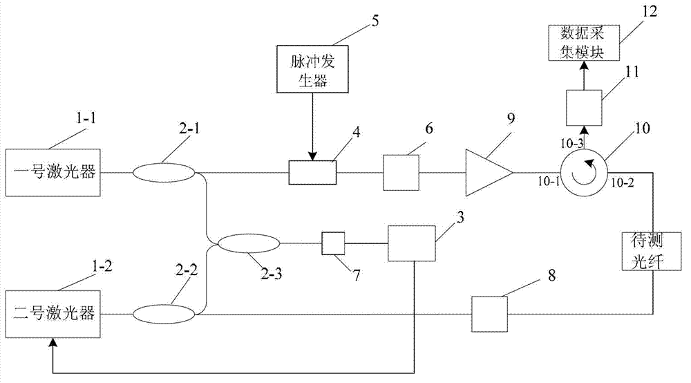
[0009] Specific implementation mode one: combine figure 1 Describe this embodiment, the Brillouin optical time domain analyzer based on the optical phase-locked loop to lock the frequency of two lasers in this embodiment, it is composed of No. 1 laser 1-1, No. 2 laser 1-2, and No. 1 optical fiber coupling 2-1, No. 2 fiber coupler 2-2, No. 3 fiber coupler 2-3, phase-locked loop module 3, electro-optic modulator 4, pulse generator 5, polarization scrambler 6, detection amplifier module 7, optical An attenuator 8, an erbium-doped fiber amplifier 9, a circulator 10, a photodetector 11 and a data acquisition module 12 are formed, and the output end of the No. 1 laser 1-1 is connected with the optical signal input end of the No. 1 fiber coupler 2-1. The optical signal output port of No. 1 fiber coupler 2-1 is connected with the optical signal input port of electro-optic modulator 4 and No. 3 fiber coupler 2-3 at the same time, and the output port of No. 2 laser 1-2 is connected with...

specific Embodiment approach 2

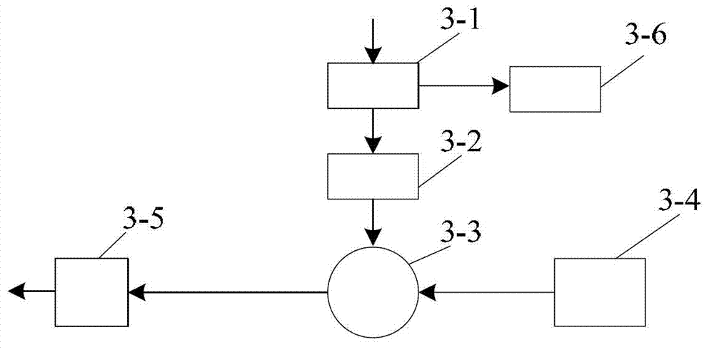
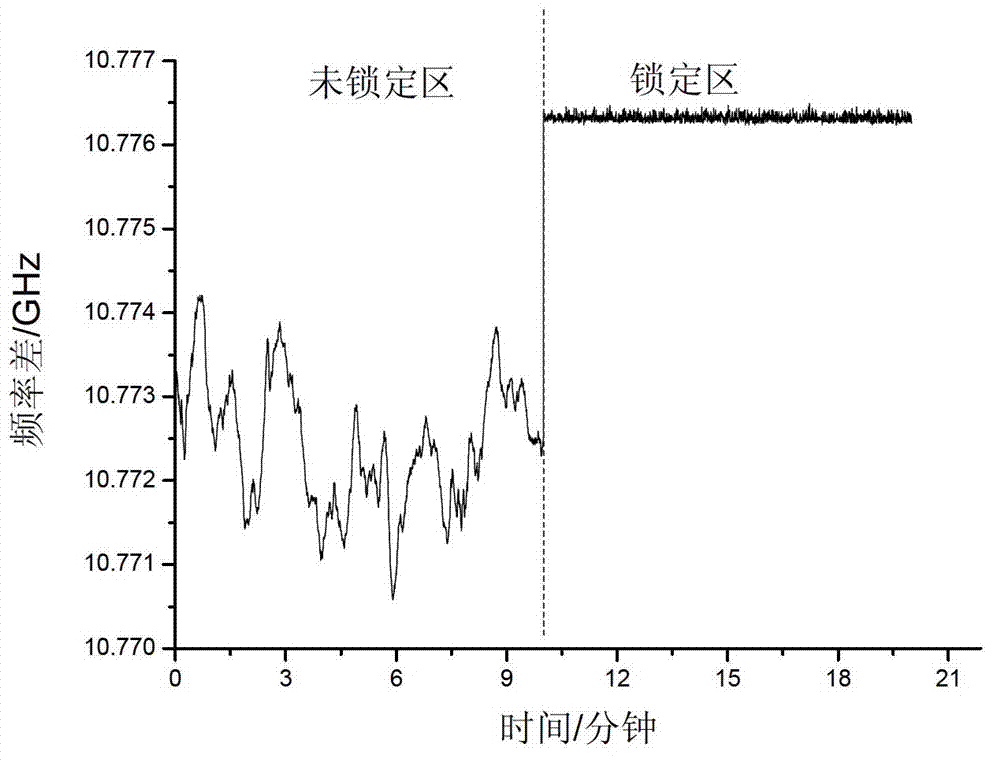
[0013] Specific implementation mode two: combination figure 2 and image 3 Describe this embodiment, this embodiment is a further limitation to the Brillouin optical time-domain analyzer based on the optical phase-locked loop locking the frequency of two lasers described in the first embodiment, the phase-locked loop module 3 is composed of a directional coupler 3- 1. Composed of frequency divider 3-2, phase / frequency discriminator 3-3, reference signal source 3-4, loop filter 3-5 and frequency counting unit 3-6, the electrical signal of directional coupler 3-1 The input end is the electrical signal input end of the phase-locked loop module 3, the output end of a signal of the directional coupler 3-1 communicates with the input end of the signal of the frequency divider 3-2, and another signal of the directional coupler 3-1 The output end of the frequency divider is communicated with the input end of the frequency counting unit 3-6; The output end of the signal of the freque...

specific Embodiment approach 3

[0016] Embodiment 3: This embodiment is a further limitation of the Brillouin optical time-domain analyzer based on the optical phase-locked loop to lock the frequency of two lasers described in Embodiment 1. No. 1 laser 1-1 and No. 2 laser 1 -2 adopts single-frequency narrow-linewidth fiber laser, distributed feedback semiconductor laser or external cavity semiconductor laser.


PUM


Abstract

The invention discloses a Brillouin optical time domain analysis meter capable of locking frequencies of two lasers based on an optical phase-locked loop, relates to a Brillouin optical time domain analysis meter, and solves the problems of high price, complicated structure and large volume of the conventional device for detecting a beat frequency signal obtained after frequency mixing of the two lasers by utilizing a microwave frequency counter, and slow frequency scanning speed and narrow frequency scanning range caused by slow response speed of an optical delay line due to frequency locking and scanning between two distributed feedback type semiconductor lasers through the optical delay line. The Brillouin optical time domain analysis meter comprises a 1# laser, a 2# laser, a 1# optical fiber coupler, a 2# optical fiber coupler, a 3# optical fiber coupler, a phase-locked loop module, an electro-optical modulator, a pulse generator, a scrambler, a detection amplification module, an optical attenuator, an erbium doped fiber amplifier, a circulator, a photoelectric detector and a data acquisition module. The invention is suitable for the Brillouin optical time domain analysis meter.

Description

technical field [0001] The invention relates to a Brillouin optical time domain analyzer. Background technique [0002] The continuous distributed Brillouin optical fiber sensor uses Brillouin scattering in the optical fiber as the sensing mechanism, which can provide distributed ultra-long distance high-resolution, high-precision strain and temperature monitoring. The sensing system uses standard optical communication optical fiber as the sensing medium, which can be used for temperature and strain monitoring as well as communication, and can realize the multiplexing of sensing and communication. The application fields of continuous distributed Brillouin fiber optic temperature and strain sensors include: temperature and deformation monitoring of oil and gas pipelines and storage tanks, temperature and strain monitoring of submarine or land high-voltage cables, geological disasters (such as landslides, debris flows, etc.) Distributed monitoring of distributed monitoring, s...

Claims


Application Information

Patent Timeline
Patent Type & Authority Applications(China)
IPC IPC(8): G01D5/36
Inventor 董永康吕志伟
Owner HARBIN INST OF TECH
Why Eureka
Try Eureka