Integrated current-interrupt device for lithium-ion cells

a current-interrupt device and lithium-ion cell technology, applied in the direction of batteries, cell components, sustainable manufacturing/processing, etc., can solve the problems of limiting the capacity of batteries by a large amount of space, compromising the reliability and safety of such batteries, etc., to achieve the effect of reducing increasing the cell capacity, and minimizing the space occupied by the cid within the batteries

Inactive Publication Date: 2008-01-10
BOSTON POWER INC
View PDF76 Cites 67 Cited by
  • Summary
  • Abstract
  • Description
  • Claims
  • Application Information

AI Technical Summary

Benefits of technology

[0010] In the batteries of the invention, at least a portion of the CID can be a part of, or external to, the battery can, because the CID is in electrical communication with the battery can, thereby minimizing the space occupied by the CID within the batteries. In addition, in some embodiments, a PTC layer typically in electrical communication with a negative terminal of the batteries, which is electrically insulated from the battery can, can be placed separately from the CID. This desi...

Problems solved by technology

Batteries that employ Li-ion cell chemistry may produce gas when they are improperly charged, shorted or exposed to high temperatures.
This gas can be combustible and may compromise the reliabi...

Method used


Image

  • Integrated current-interrupt device for lithium-ion cells
  • Integrated current-interrupt device for lithium-ion cells
  • Integrated current-interrupt device for lithium-ion cells

Examples


Embodiment Construction

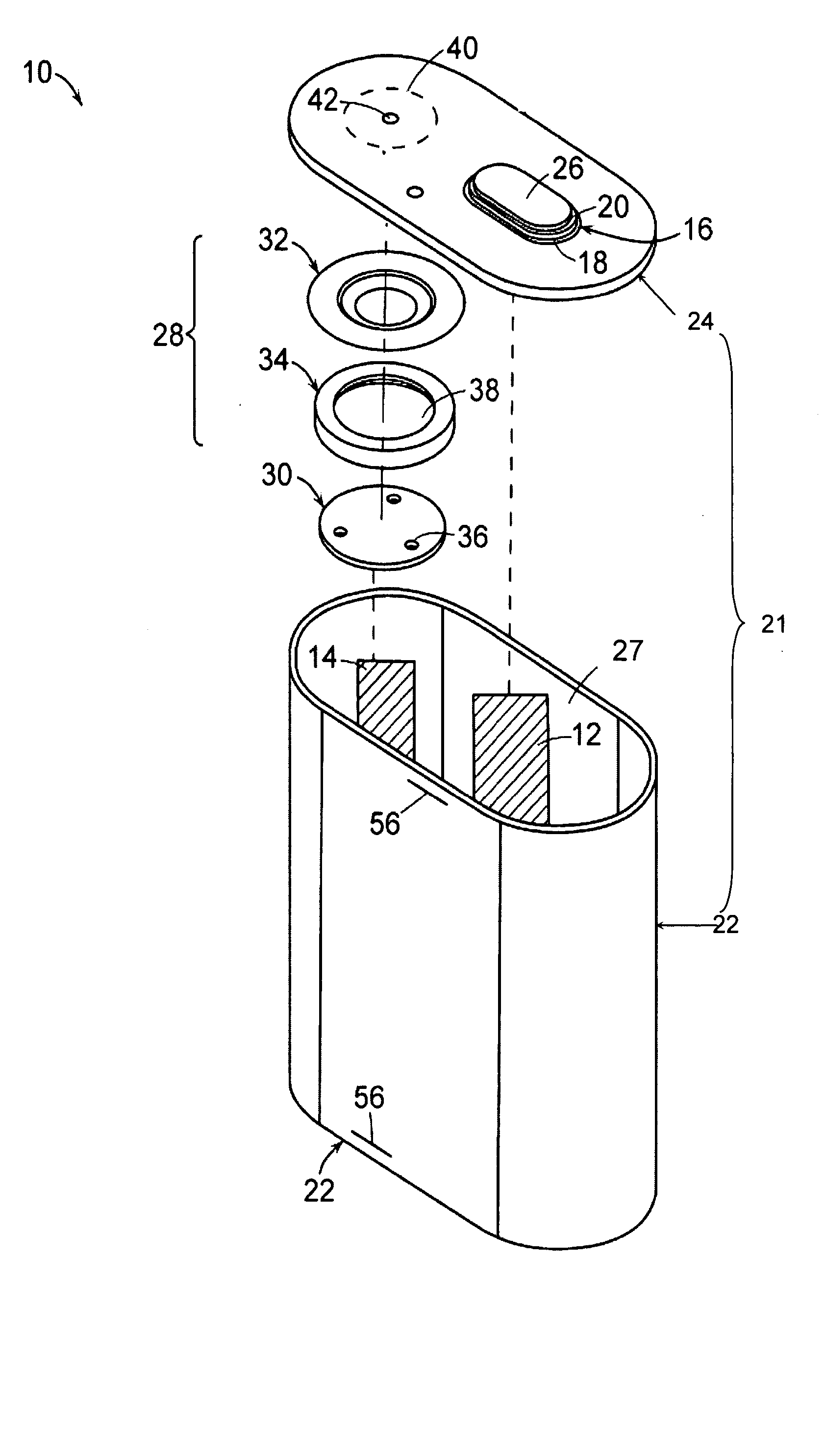
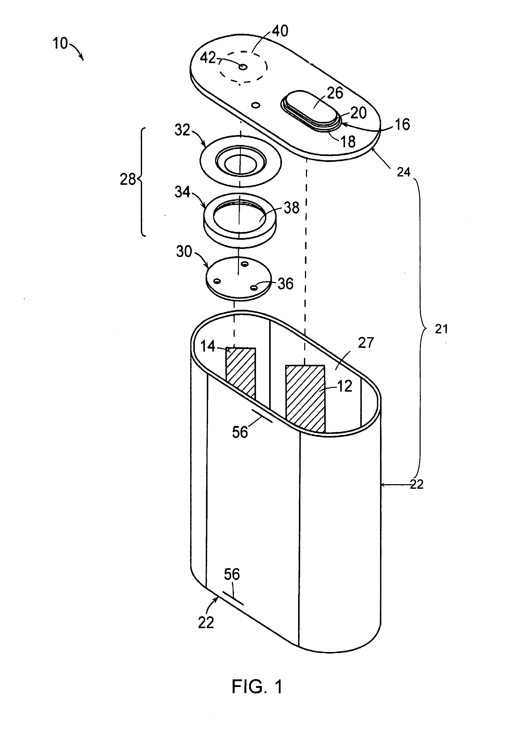
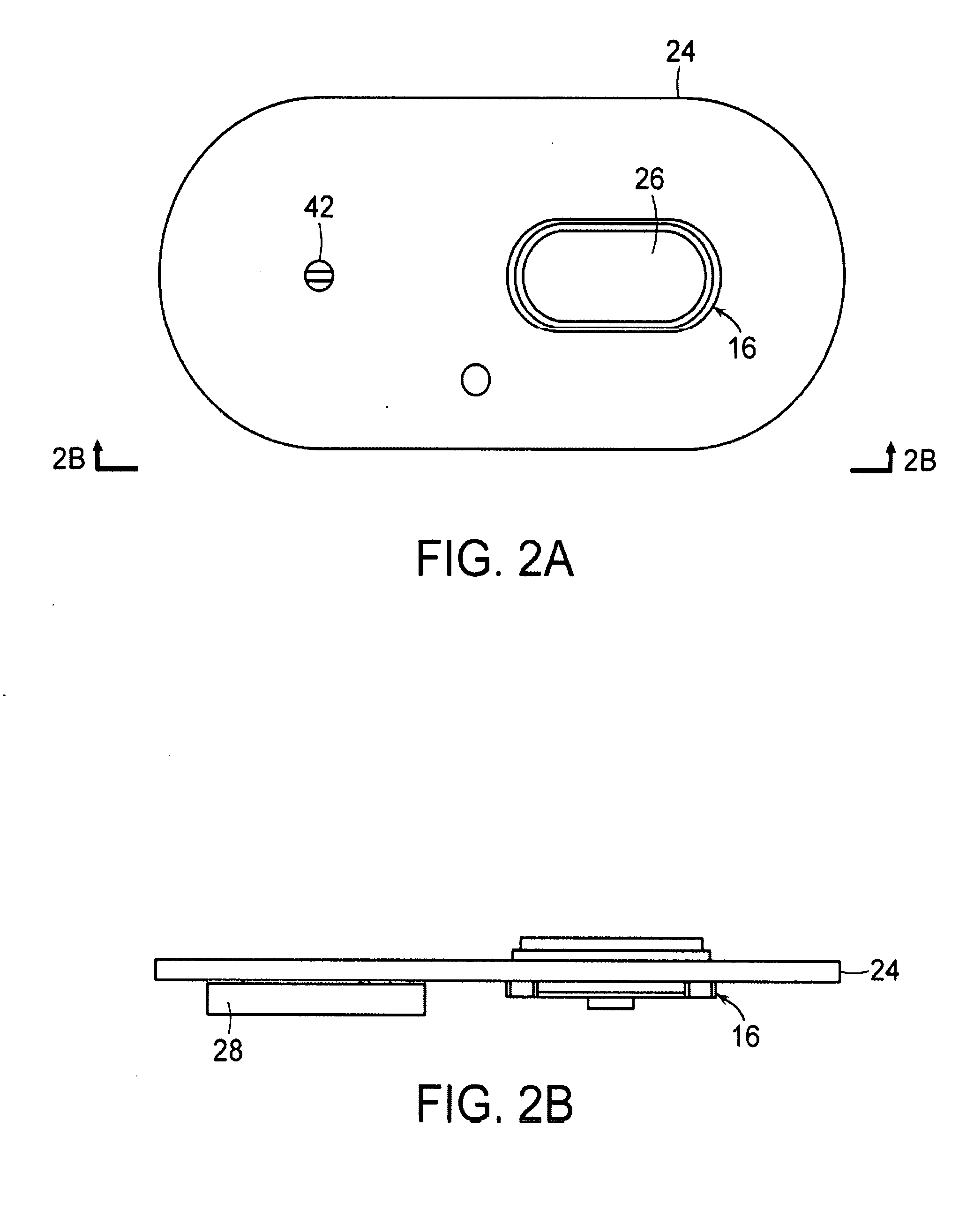
[0017] The foregoing will be apparent from the following more particular description of example embodiments of the invention, as illustrated in the accompanying drawings. The drawings are not necessarily to scale, emphasis instead being placed upon illustrating embodiments of the present invention.

[0018] As used herein, the “terminals” of the batteries of the invention mean the parts or surfaces of the batteries to which external electric circuits are connected.

[0019] The batteries of the invention typically include a first terminal in electrical communication with a first electrode, and a second terminal in electrical communication with a second electrode. The first and second electrodes are contained within the cell casing of a battery of the invention, for example, in a “jelly roll” form. The first terminal can be either a positive terminal in electrical communication with a positive electrode of the battery, or a negative terminal in electrical communication with a negative el...


PUM

PropertyMeasurementUnit
Currentaaaaaaaaaa
Shapeaaaaaaaaaa
Electrical conductoraaaaaaaaaa

Abstract

A battery comprises a first terminal in electrical communication with a first electrode of the battery, a second terminal in electrical communication with a second electrode of the battery, a battery can electrically insulated from the first terminal, and at least one current interrupt device in electrical communication with the battery can. The battery can includes a cell casing and a lid which are in electrical communication with each other. At least a portion of the battery can is at least a component of the second terminal, or is electrically connected to the second terminal. The current interrupt device includes a first conductive plate in electrical communication with the second electrode, and a second conductive plate in electrical communication with the first conductive plate. The second conductive plate separates from the first conductive plate when pressure inside the battery is greater than a predetermined value, whereby a current flow between the second electrode and the second terminal is interrupted.

Description

RELATED APPLICATION [0001] This application claims the benefit of U.S. Provisional Application No. 60 / 816,775, filed Jun. 27, 2006, the entire teachings of which are incorporated herein by reference. INCORPORATION BY REFERENCE [0002] U.S. patent application, filed on Jun. 22, 2007 under Attorney's Docket No. 3853.1015-000, which is entitled “Low Pressure Current Interrupt Device For Batteries”; International Application, filed on Jun. 22, 2007 under Attorney's Docket No. 3853.1001-015, entitled “Lithium-Ion Secondary Battery”; U.S. Provisional Application No. 60 / 717,898, filed on Sep. 16, 2005; International Application No. PCT / US2005 / 047383, filed on Dec. 23, 2005; U.S. patent application Ser. No. 11 / 474,081, filed on Jun. 23, 2006; U.S. patent application Ser. No. 11 / 474,056, filed on Jun. 23, 2006; U.S. Provisional Application No. 60 / 816,977, filed on Jun. 28, 2006; U.S. patent application Ser. No. 11 / 485,068, filed on Jul. 12, 2006; U.S. patent application Ser. No. 11 / 486,970, f...

Claims


Application Information

Patent Timeline
IPC IPC(8): H01M6/02H01M2/04H01M6/42H01M2/14H01M10/052H01M10/36H01M50/119H01M50/574
CPCH01M2/0285H01M2/34H01M2/345H01M6/42Y10T29/49108H01M10/052H01M2200/10H01M2200/20Y02T10/7011H01M10/04Y02E60/10H01M50/578Y02P70/50H01M10/058H01M50/574H01M50/119H01M10/0525H01M50/572
Inventor PARTIN, PHILLIP E.ZENG, SHERMAN H.ONNERUD, PERSONG, YANNINGCHAMBERLAIN, RICHARD V. II
Owner BOSTON POWER INC
Why Eureka
Try Eureka