Eureka AIR delivers breakthrough ideas for toughest innovation challenges, trusted by R&D personnel around the world.

Dental holder

a technology for firing platforms and dental trays, applied in dentistry, medical science, dental prostheses, etc., can solve the problems of difficult to achieve, difficult to transfer coping, and more difficult, and achieve the effect of saving time, good surface mounting area and configuration, and facilitating the preparation of dental prostheses

Inactive Publication Date: 2008-01-10
MURSIC JONATHAN CARL
View PDF4 Cites 7 Cited by
  • Summary
  • Abstract
  • Description
  • Claims
  • Application Information

AI Technical Summary

Benefits of technology

[0006] In accordance with another aspect of the present invention, there is no need to transfer the prosthesis from a dental holder to a new firing tray.
[0031] In accordance with another aspect of the present invention, there is provided a use of an apparatus for holding a dental prosthesis during preparation of the prosthesis and for holding the dental prosthesis during firing without having to transfer the prosthesis to a second tray for firing.

Problems solved by technology

Current products that provide for holding the prosthesis while it is fired in a furnace have the disadvantage that the coping must be transferred to the firing platform without touching the unfired product application which is difficult to accomplish.
When a large prosthesis like a bridge framework is being transferred it is even more difficult.
Existing firing trays cannot practicably be used as holders because current prosthesis wires do not provide a suitable mounting means to the tray to ensure stability especially with the narrow, pointed pins presently used for holding substructure for the prosthesis.

Method used


Image

  • Dental holder
  • Dental holder
  • Dental holder

Examples


Embodiment Construction

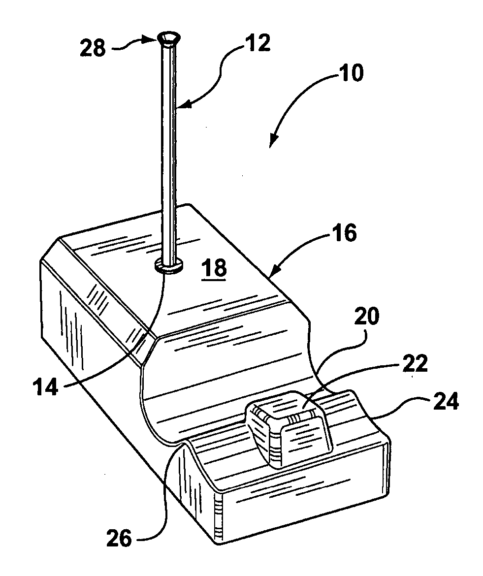
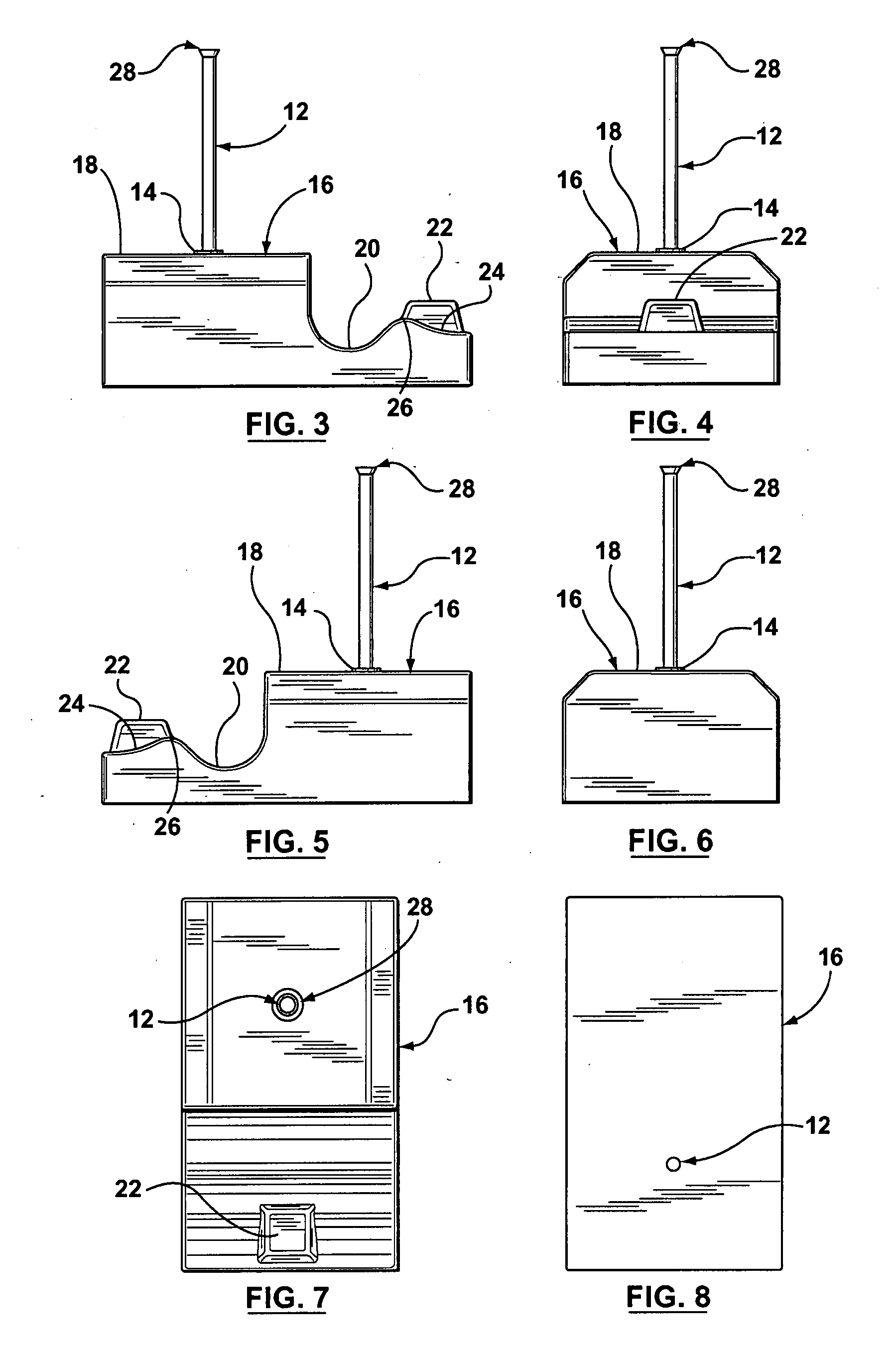
[0127] The apparatus device of the present invention is used to securely hold and fire a dental prosthesis from beginning to end of the dental prosthesis creation.

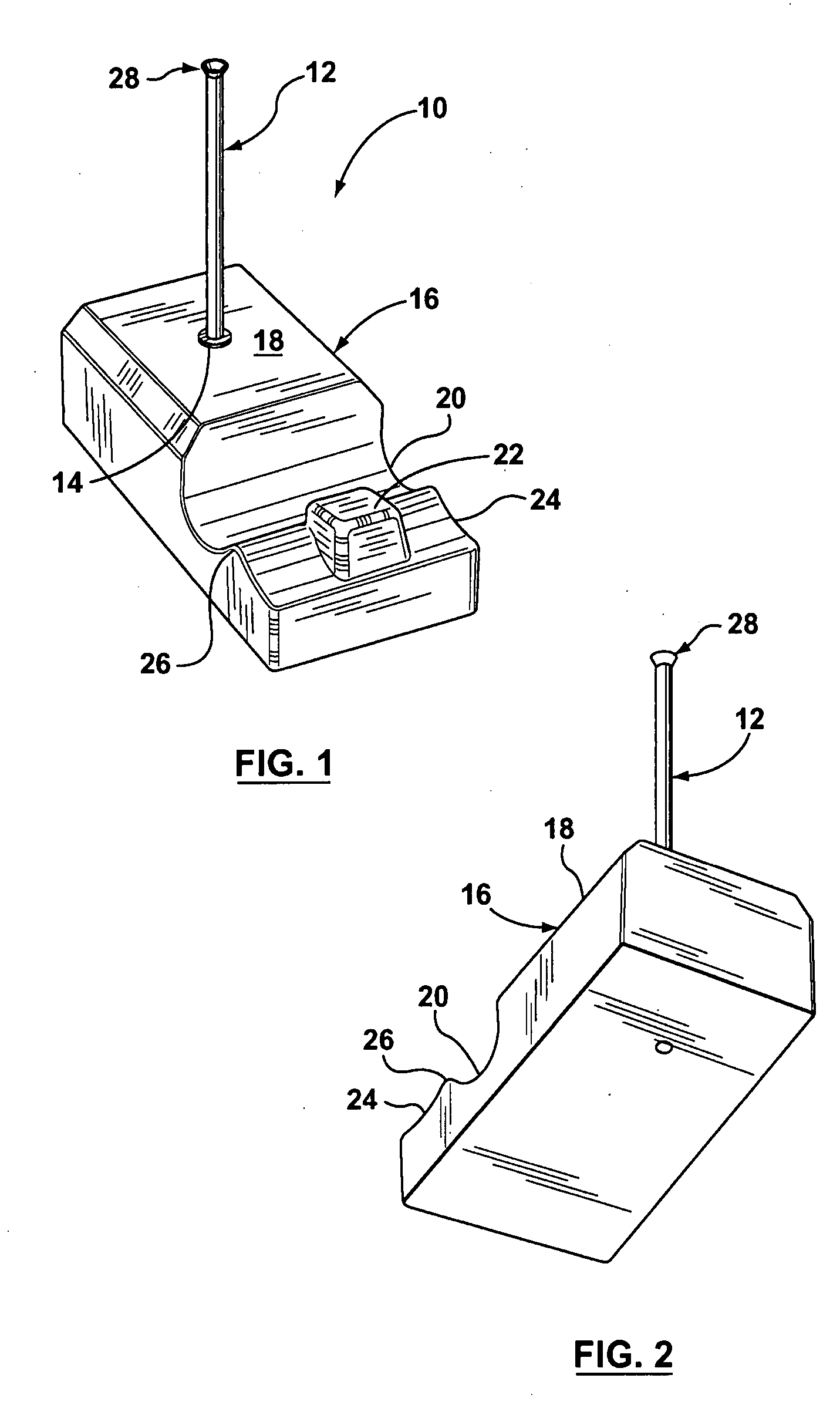
[0128] The dental holder of the present invention comprises a unique pin with a curved, cup shaped portion at one end. This shaped portion could also be described as flared or even “saucer” shaped. It is this curved, cupped shape is like a saucer at the end of the pin. While it would be possible to spot weld a “saucer” element to the end of a traditional pin, it is preferred that the pin be prepared such that this shape is an integral portion when the shape of the end of the at least one pin is an integral portion of the pin it would appear as illustrated in the Figures. The pin and cup portion can be made of any suitable material as known to a person skilled in the art including materials such as plastic, aluminum and stainless steel.

[0129] The holder comprises one or more of the inventive pins of the present invention ...


PUM


Abstract

An apparatus for holding a dental prosthesis during preparation of the dental prosthesis, the apparatus comprising: at least one base, the at least one base having an upper surface, at least one pin, and the at least one pin comprising a first end and a second end, the at least one pin further comprising a flared portion at the first end, and the first end extending beyond the upper surface of the at least one base, and the second end extending through and into the upper surface of the base. The use of an apparatus for holding a dental prosthesis during preparation of the prosthesis and for holding the dental prosthesis during firing without having to transfer the prosthesis to a second tray for firing. A method for preparing a dental prosthesis, the method comprising the steps of: a) mounting a substructure on an apparatus comprising at least one base, the at least one base having an upper surface, at least one pin, and the at least one pin comprising a first end and a second end, the at least one pin further comprising a flared portion at the first end, and the first end extending beyond the upper surface of the at least one base, and the second end extending through and into the upper surface of the base, b) applying at least one layer of ceramic to prepare a dental prosthesis, and c) firing the prosthesis mounted on the apparatus in a furnace.

Description

FIELD OF THE INVENTION [0001] This invention relates to a dental holder firing platform apparatus to hold a dental prosthesis or substructure for preparation of a dental prosthesis. This invention further relates to a dental holder firing platform which can be used both as a dental holder and as a firing tray or platform thereby eliminating the need to transfer the final prepared dental prosthetic from a holding tray to a firing tray prior to firing the dental prosthesis in a furnace. The invention further relates to a method for preparing a dental prosthesis using a stand alone dental holder firing platform apparatus. The invention further relates to a pin for mounting a dental prosthesis on a dental holder. BACKGROUND OF THE INVENTION [0002] Current devices and apparatus used in the application of porcelain in the preparation of a dental prosthesis require that the prosthesis be transferred from a holding device to a firing tray prior to firing in a furnace. This transfer step req...

Claims


Application Information

Patent Timeline
Patent Type & Authority Applications(United States)
IPC IPC(8): A61C13/08
CPCA61C13/12
Inventor MURSIC, JONATHAN CARL
Owner MURSIC JONATHAN CARL
Why Eureka
Eureka Blog
Learn More