Method and apparatus for controlling a contiuously variable transmission

a technology of contiuously variable transmission and transmission shaft, which is applied in mechanical apparatus, digital data processing details, instruments, etc., can solve the problems of undesirable lurching motion, vehicle lurching to such an extent, and inability smooth operation, so as to achieve a smooth operation

Inactive Publication Date: 2008-01-10
EATON INTELLIGENT POWER LTD
View PDF20 Cites 53 Cited by
  • Summary
  • Abstract
  • Description
  • Claims
  • Application Information

AI Technical Summary

Benefits of technology

[0011]According to one aspect of the present invention, a method is provided for controlling the ratio of a continuously variable transmission that is controlled by a CVT controller. The method comprises determining the torque produced by an engine to develop a torque value. An acceleration limit value is calculated by dividing the torque value by an engine inertia value and multiplying by a limiting ratio. The acceleration limit value is then compared to a desired engine speed value to determine a command engine speed value. The CVT ratio is calculated by dividing the command engine speed value by a measured speed value. The CVT ratio is compared to a measured CVT ratio and a control signal is sent to an actuator of the CVT, whereby torque provided to the engine to overcome the engine's inertia is limited so that the step change in torque provided to the wheels of a vehicle as the engine approaches the command engine speed is reduced.

Problems solved by technology

An undesirable lurching motion may occur when acceleration of the engine to the desired vehicle speed is completed.
When torque to the wheels spikes, it causes the vehicle to lurch to such an extent it may be felt by a driver or passenger.
It is generally considered to be undesirable to reduce the acceleration of the engine because such a reduction in turn reduces acceleration of the vehicle.
This may cause the CVT to begin variating before the target speed is reached.

Method used


Image

  • Method and apparatus for controlling a contiuously variable transmission
  • Method and apparatus for controlling a contiuously variable transmission
  • Method and apparatus for controlling a contiuously variable transmission

Examples


Embodiment Construction

)

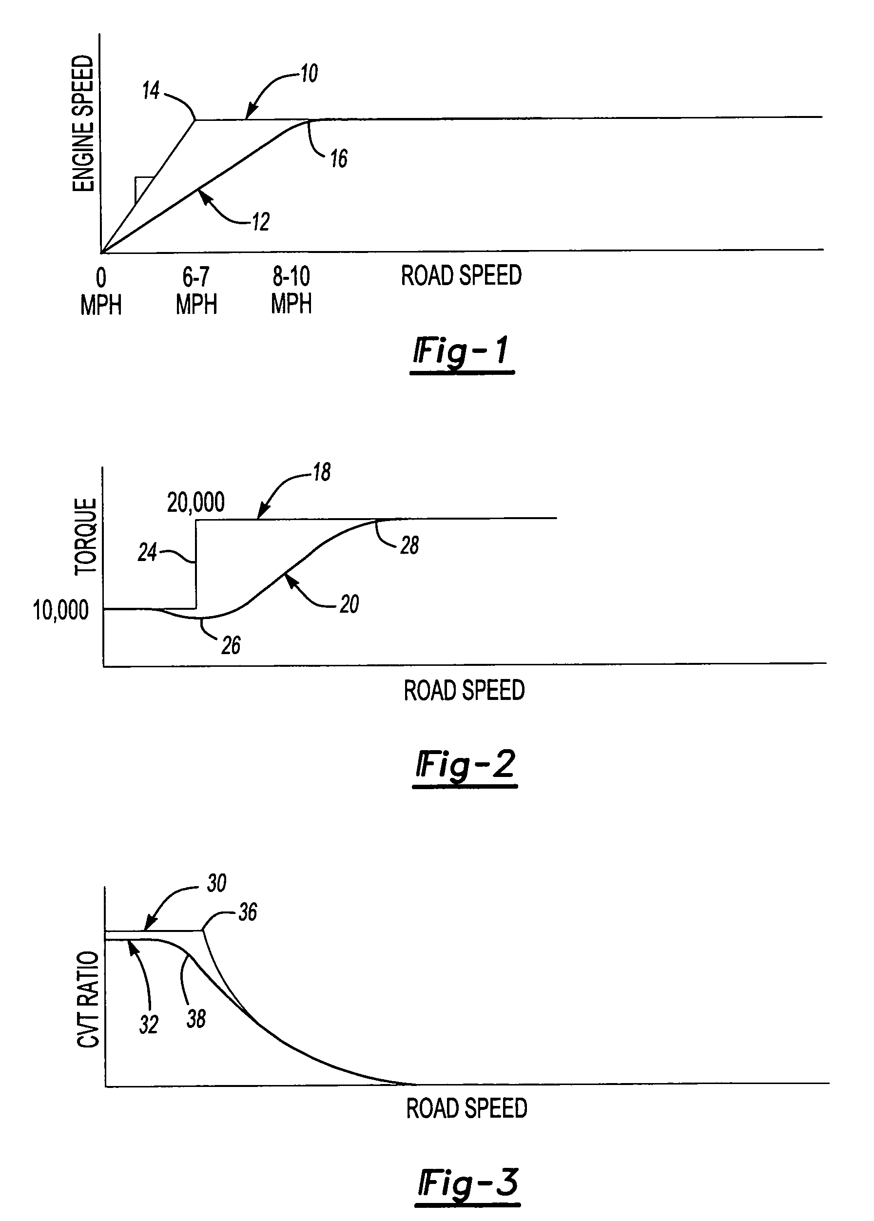
[0022]Referring to FIG. 1, a graph is provided that compares a normal acceleration from launch curve 10 to a rate limited acceleration from launch curve 12. A normal transition point 14 represents the transition in engine speed as it accelerates from launch to the running rpm, or constant rpm, level. For example, as an engine accelerates from launch or zero engine speed to 1,400 rpm, the engine accelerates at a relatively rapid rate to overcome engine inertia. At the normal transition point 14, the vehicle may undesirably lurch forward due to a step change in torque that will be described with reference to FIG. 2. The rate limited acceleration from launch curve 12 has a rate limited transition period 16 that provides a more gradual transition from engine acceleration to the constant engine speed. Engine acceleration is lower during the launch curve 12 resulting in the engine providing less torque change in transition. Acceleration is more gradual with the rate limited acceleration ...


PUM


Abstract

A method of controlling the ratio of a continuously variable transmission (CVT) that is controlled by a CVT controller is provided. The method includes determining the torque produced by an engine, calculating an acceleration limit value based upon the torque value and the engine inertia value and a calibrated acceleration limiting ratio. The acceleration limit value is compared to the desired engine speed value to determine a command engine speed value. The CVT ratio is then calculated by dividing the command engine speed value by a measured vehicle speed value. The calculated CVT ratio is compared to a measured CVT ratio and a control signal is sent to an actuator of a CVT. Torque provided to the engine to overcome the engine inertia is limited by the method so that the step change in torque provided to the vehicle wheels, as the engine approaches the command engine speed value, is reduced.

Description

BACKGROUND OF THE INVENTION[0001]1. Field of the Invention[0002]The present invention relates to a method and apparatus for controlling a continuously variable transmission during vehicle launch at low speeds to allow acceleration to a desired vehicle speed while providing a smooth ride.[0003]2. Background Art[0004]A continuously variable transmission (CVT) may be used to transfer torque from an engine to a vehicle's wheels. A CVT may comprise a drive sheave wheel and a driven sheave wheel that engage a drive belt or chain and are dynamically adjusted. The effective diameter of the drive sheave wheel and the driven sheave wheel may be varied according to a desired CVT ratio. The CVT ratio is the ratio of the drive sheave wheel effective diameter to the driven sheave wheel effective diameter. Rotation of the drive wheel is transferred to the driven wheel by the CVT belt or chain.[0005]One of the benefits of a CVT is that the CVT may be controlled by a CVT controller to permit the eng...

Claims


Application Information

Patent Timeline
Patent Type & Authority Applications(United States)
IPC IPC(8): B60W10/04
CPCF16H61/66254Y10T477/619Y10T477/623F16H61/66259
Inventor JACOBS, CRAIG S.
Owner EATON INTELLIGENT POWER LTD
Why Eureka
Try Eureka