Pedicle screw distractor and associated method of use

a technology of distractor and pedicle screw, which is applied in the field of spinal fixation devices, can solve the problems of complex and bulky pedicle screw distractors in the prior art, and achieve the effects of convenient and simple distraction process, convenient and simple seating of spacers, and simple structur

Inactive Publication Date: 2008-01-10
ZIMMER SPINE INC
View PDF24 Cites 117 Cited by
  • Summary
  • Abstract
  • Description
  • Claims
  • Application Information

AI Technical Summary

Benefits of technology

[0008]This invention addresses these and other shortcomings in the prior art. In one embodiment, the invention is an instrument in the form of a distractor for the pedicle screw to aid surgeons in counteracting the compressive force on the spacer between the pedicle screws and assist in the process of seating the spacer. The invention also is directed to a method for seating the spacer between the pedicle screws. Most pedicle screw distractors available in the prior art are complex and bulky and require attachment to two pedicle screw heads to perform the distraction. This invention provides a simple one-piece distractor design that only requires engagement with one of the pedicle screw heads for distraction. The instrument according to this invention cooperates with existing instrumentation to distract the pedicle screw heads for simple, efficient and accurate seating of the spacer.
[0009]The pedicle screw distractor according to one embodiment includes a head specifically designed and adapted to engage one of the pedicle screws seated in the patient's spine. The head in one embodiment includes a bifurcated yoke having a concave seat adapted to receive a convex-shaped head of the pedicle screw. A lever extends from the head of the pedicle screw distractor and is joined to a handle of the instrument to form a fulcrum arrangement at the juncture between the lever and the handle. A saddle is provided at the fulcrum and is adapted to receive and seat the instrument on the shaft or body of another instrument mounted to an adjacent pedicle screw. The pedicle screw distractor when seated against the accompanying instrument and the installed pedicle screws provides for a convenient and simple distraction process by squeezing the handle toward the companion instrument thereby temporarily distracting the pedicle screws and providing access between the adjacent pedicle screws to seat the spacer of the spinal stabilization system there between.

Problems solved by technology

Most pedicle screw distractors available in the prior art are complex and bulky and require attachment to two pedicle screw heads to perform the distraction.

Method used


Image

  • Pedicle screw distractor and associated method of use
  • Pedicle screw distractor and associated method of use
  • Pedicle screw distractor and associated method of use

Examples


Embodiment Construction

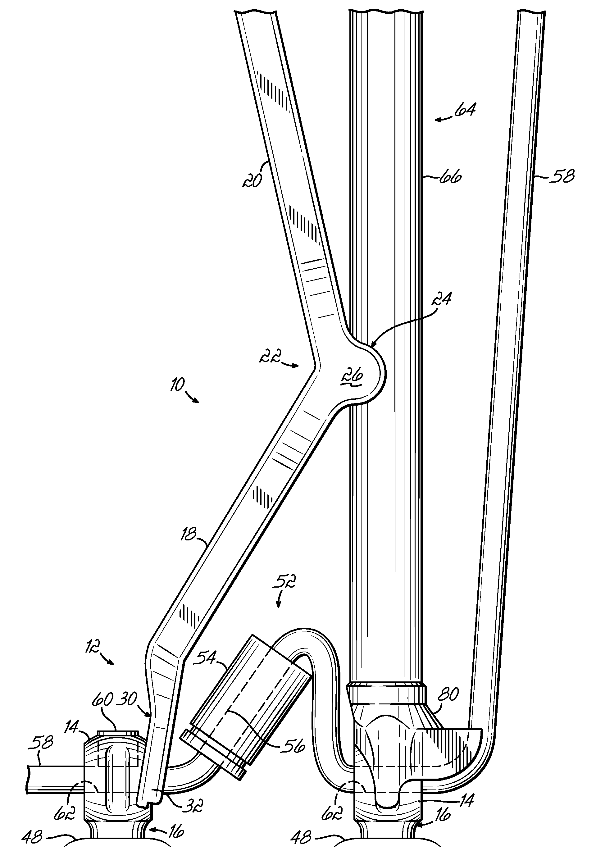
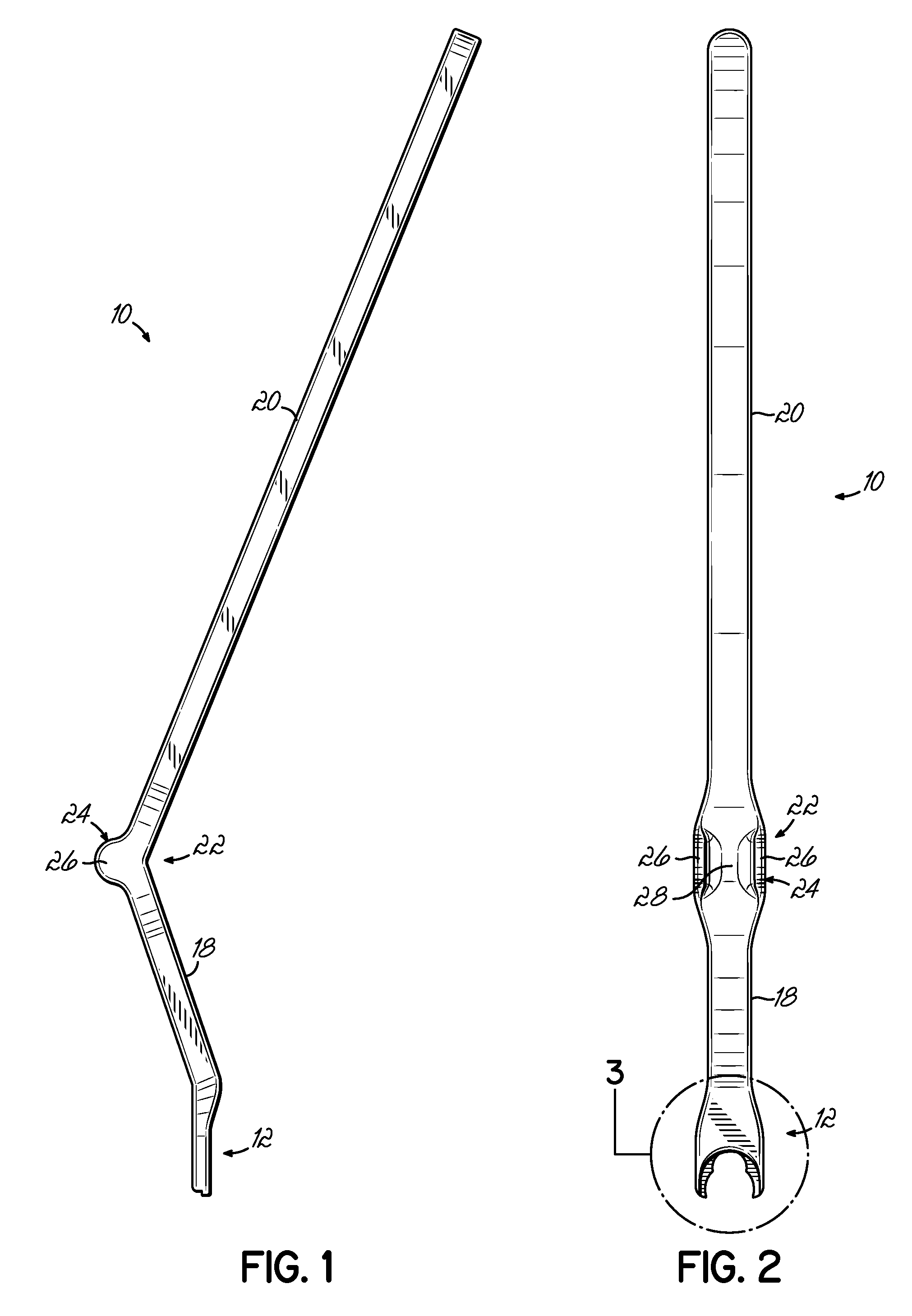
[0018]Referring to FIG. 1, one embodiment of a pedicle screw distractor 10 according to this invention is shown. The distractor 10 includes a head 12 adapted to receive a convex-shaped head 14 of a pedicle screw 16 (FIG. 6). The head 12 is joined to a lever 18 of the pedicle screw distractor 10. A handle 20 of the distractor 10 projects from a fulcrum arrangement 22 positioned at a juncture between the handle 20 and the lever 18. A saddle 24 is formed at the fulcrum 22 between the lever 18 and the handle 20 and includes a pair of spaced flanges 26 forming a channel 28 there between as shown in FIG. 2. While a variety of orientations and configurations of the pedicle screw distractor 10 are available according to this invention, a longitudinal axis of the handle 20 in one embodiment forms approximately an 138° angle with respect to a longitudinal axis of the lever 18.

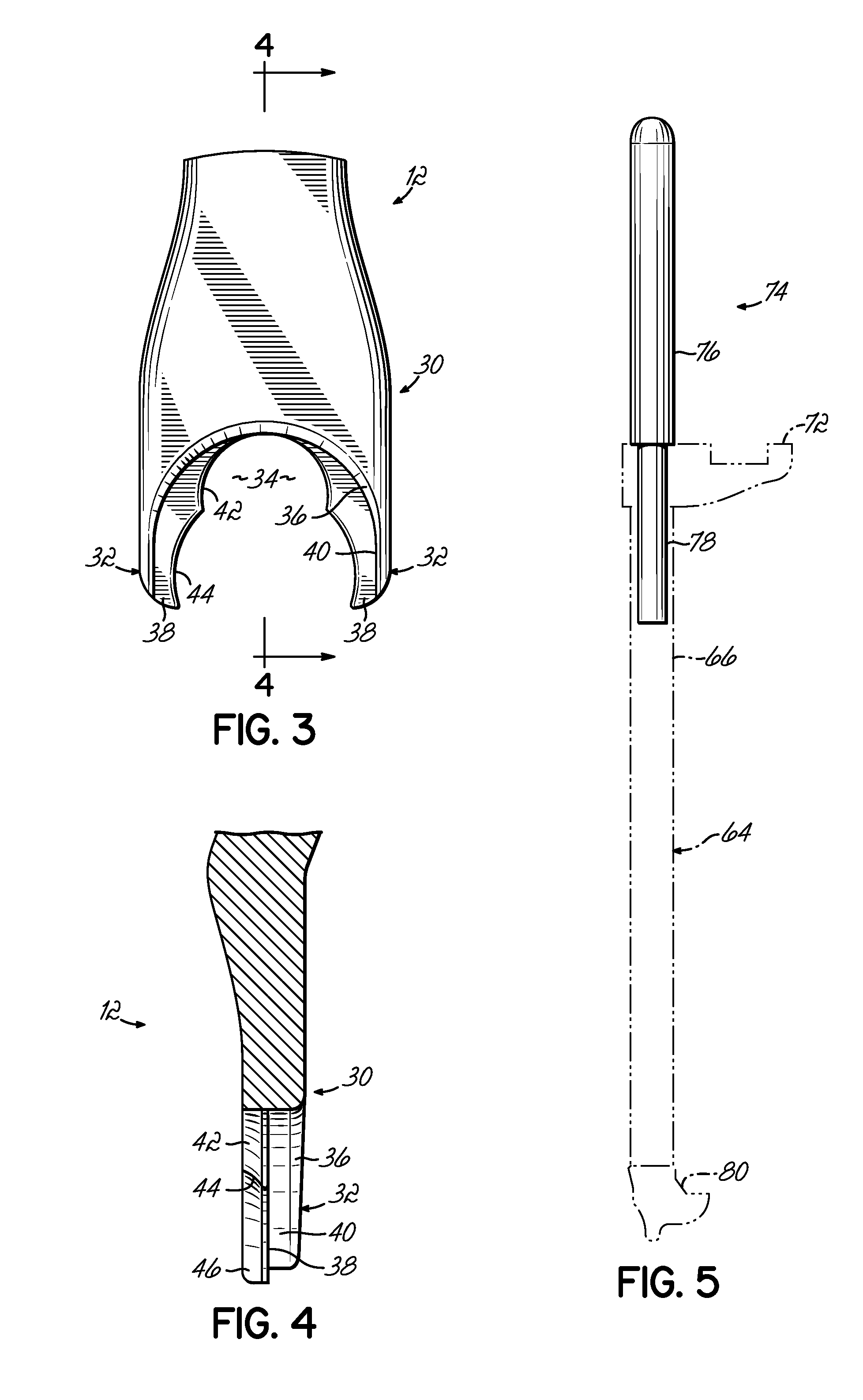
[0019]The head 12 of the distractor 10 is shown in more detail in FIGS. 2-4 and includes a bifurcated yoke 30 with a p...


PUM


Abstract

A distractor for pedicle screws aids surgeons in counteracting the compressive force on a spacer between the pedicle screws and assists in the process of seating the spacer as part of a spinal dynamic stabilization system. The distractor cooperates with existing instrumentation to distract the pedicle screw heads for simple, efficient and accurate seating of the spacer. The pedicle screw distractor includes a head specifically designed and adapted to engage one of the pedicle screws seated in the patient's spine. A lever extends from the head of the pedicle screw distractor and is joined to a handle of the instrument to form a fulcrum arrangement. A saddle is provided at the fulcrum and is adapted to receive and seat the instrument on the shaft or body of another instrument mounted to an adjacent pedicle screw. The pedicle screw distractor when seated against the accompanying instrument and the installed pedicle screws provides for a convenient and simple distraction process by squeezing the handle toward the companion instrument thereby temporarily distracting the pedicle screws and providing access between the adjacent pedicle screws to seat the spacer of the spinal stabilization system there between.

Description

TECHNICAL FIELD[0001]This invention relates generally to spinal fixation devices and more specifically relates to a system and associated method for distracting pedicle screws as part of the installation of spinal fixation devices.BACKGROUND[0002]The human spinal column is a highly complex system of bones and connective tissues that provides support for the body and protects the delicate spinal cord and nerves. The spinal column includes a series of vertebrae stacked one atop the other. Each vertebral body includes a relatively strong cortical bone portion forming the outside surface of the body and a relatively weak cancellous bone portion forming the center of the body. An intervertebral disc is situated between each vertebral body that provides for cushioning and dampening of compressive forces applied to the spinal column. The vertebral canal containing the delicate spinal cords and nerves is located just posterior to the vertebral bodies.[0003]Various types of spinal column dis...

Claims


Application Information

Patent Timeline
Patent Type & Authority Applications(United States)
IPC IPC(8): A61F2/30
CPCA61B17/025A61B2017/0256A61B17/8869A61B17/7079
Inventor BOND, MEREDITH L.DANT, JACK A.
Owner ZIMMER SPINE INC
Why Eureka
Try Eureka