
Fill tube-flange assembly for ring laser gyroscope block

a technology of laser gyroscope and fill tube, which is applied in the direction of hose connection, mechanical equipment, instruments, etc., can solve the problems of affecting the performance of the gyroscope, the welding process is tedious, and the construction of the ring laser gyroscope is expensiv

Inactive Publication Date: 2008-01-17
HONEYWELL INT INC
View PDF16 Cites 3 Cited by
  • Summary
  • Abstract
  • Description
  • Claims
  • Application Information

AI Technical Summary

Problems solved by technology

However, construction of these ring laser gyroscopes is expensive, and includes construction of numerous ancillary parts that are not included or are only partially included in the finished ring laser gyroscope.
The welding process is tedious because the fill tube and flange may be formed from different alloys, and also because particulates from the welding process may end up within the fill tube portion.
Any welding particulates that may end up within the laser block as a result of the welding process could be detrimental to operation of the finished ring laser gyroscope product.
This process of breaking off the fluid port and a portion of the fill tube is thought to be inefficient as this welded flange portion may be discarded after the processing of only one gyroscope block.
In one known process, the fluid port may be re-welded to a fill tube up to four times. However, such a large amount of processing by personnel raises costs and with each additional weld, the fluid port has an increased possibility of becoming compromised.

Method used


Image

  • Fill tube-flange assembly for ring laser gyroscope block
  • Fill tube-flange assembly for ring laser gyroscope block
  • Fill tube-flange assembly for ring laser gyroscope block

Examples


Embodiment Construction

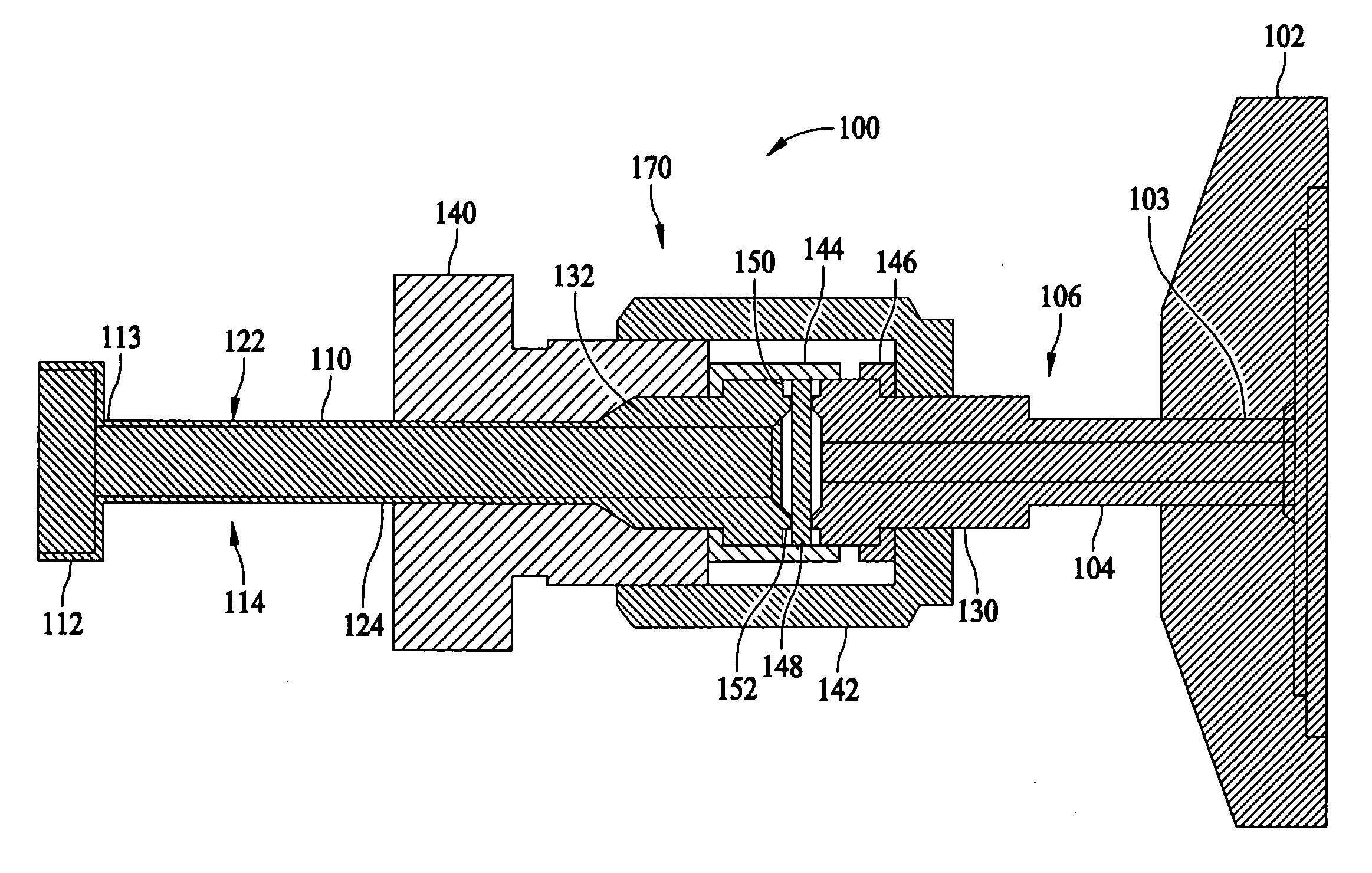
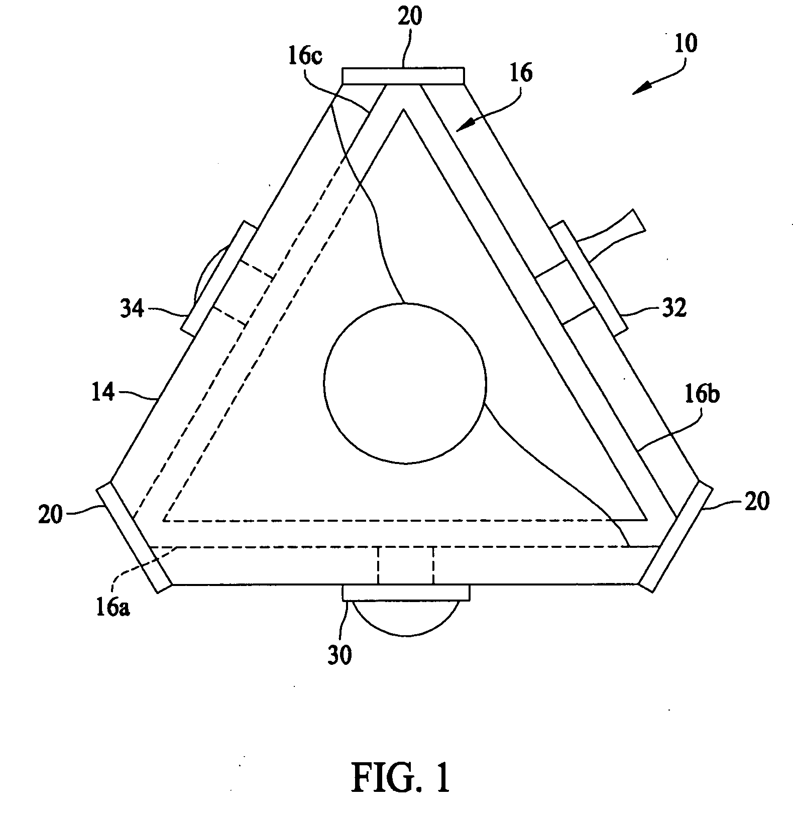
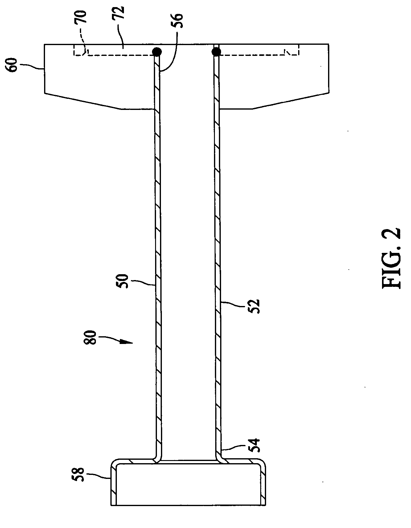
[0013]A representative laser block assembly 10 which can be processed using the below described fill tube / flange assembly is shown in FIG. 1. However, it is to be understood that other types of laser block assemblies can also be processed using the fill tube / flange assembly in accordance with the invention. Laser block assembly 10 includes a laser block 14 having an optical closed loop pathway 16 comprising a plurality of interconnected passages 16a, 16b, and 16c (shown partially in phantom). Reflective surfaces, such as mirrors 20, are positioned and appropriately angled at the intersection of the individual passages 16a, 16b, and 16c to reflect light from one passage into another passage. Excitation electrodes 30, 32, and 34 are mounted to laser block 14 in fluid communication with the closed loop path 16. Closed loop passage 16 is filled with a lasing gas, such as a mixture of helium and neon, through one of the electrodes appropriately fitted with a fluid port configured to inte...


PUM


Abstract

A fill tube and flange assembly for fabrication of ring laser gyroscope blocks is described. The assembly includes a flange assembly, a fill tube assembly, and a compression interface. The flange assembly includes a flange tube and a fluid port at a first end of the flange assembly tube. The fill tube assembly includes a fill tube and a laser block engaging portion at a first end of the fill tube. The compression interface is configured to couple second ends of the fill tube and the flange assembly tube.

Description

BACKGROUND OF THE INVENTION[0001]This invention relates generally to fabrication of ring laser gyroscopes, and more particularly, to a fill tube and flange assembly that is utilizing in the processing of the bores of the laser block, for example, with a gas used in the generation of a laser beam within the block.[0002]Ring laser gyroscopes are well known and are widely utilized in aerospace systems, weapons delivery systems, and multiple other applications. However, construction of these ring laser gyroscopes is expensive, and includes construction of numerous ancillary parts that are not included or are only partially included in the finished ring laser gyroscope.[0003]One of these ancillary parts is a fill tube welded to a flange. This assembly, as the name implies, is fabricated by welding a flange onto a fill tube. The welding process is tedious because the fill tube and flange may be formed from different alloys, and also because particulates from the welding process may end up...

Claims


Application Information

Patent Timeline
IPC IPC(8): F16L19/00
CPCG01C19/661
Inventor STAY, CHAD P.JARRETT, MARK JAY
Owner HONEYWELL INT INC
Learn More