Magnetic Stirrer

a magnetic stirrer and stir bar technology, applied in the field of magnetic stirrers, can solve the problems of stir bar decoupling from the base magnet, adverse effects of conditions, and traditional base magnets not being strong enough to handle these conditions

Inactive Publication Date: 2008-01-17
SIGMA ALDRICH CO LLC
View PDF15 Cites 28 Cited by
  • Summary
  • Abstract
  • Description
  • Claims
  • Application Information

AI Technical Summary

Problems solved by technology

Traditional base magnets are often not strong enough to handle these conditions.
In many cases, the coupling force between a traditional base magnet and the stir bar fails, resulting in the stir bar decoupling from the base magnet.
These conditions can be adversely impacted by the components / design of the stirrer.
For example, stirrer designs that have multiple joints or must be sealed would not function well in high vacuums.
Similarly, electric motors would not be desirable where highly volatile chemicals are being used (e.g., where flammable or explosive materials are used).

Method used


Image

  • Magnetic Stirrer
  • Magnetic Stirrer
  • Magnetic Stirrer

Examples


Embodiment Construction

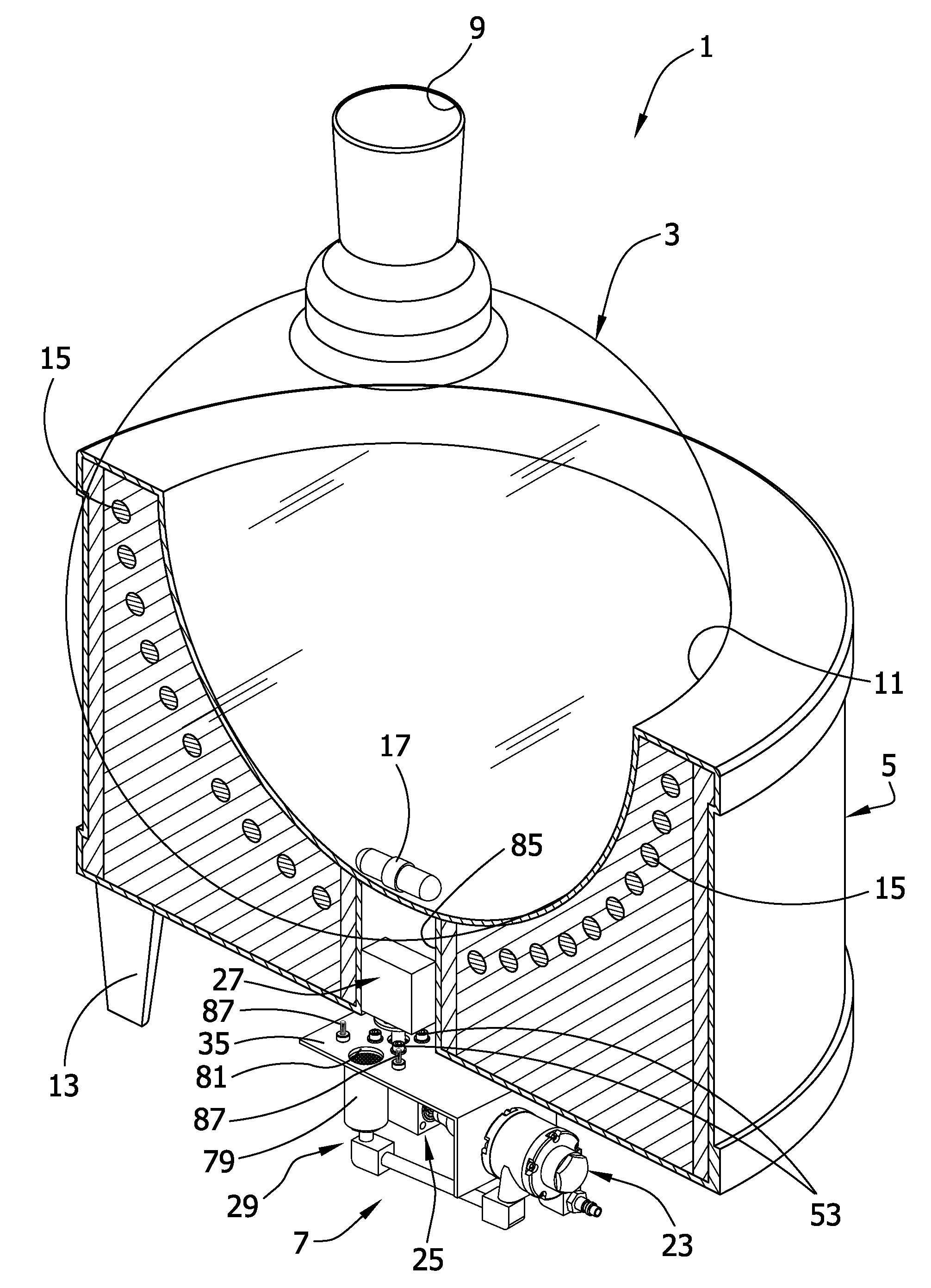
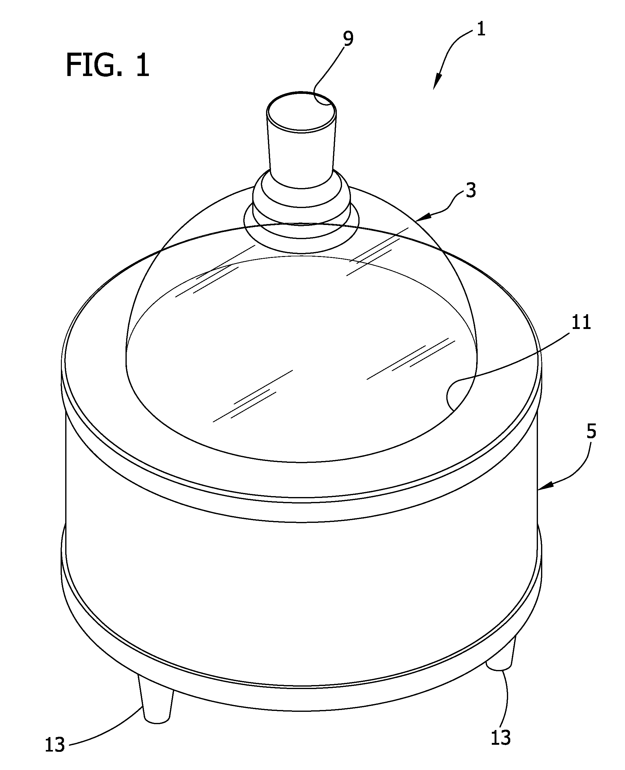
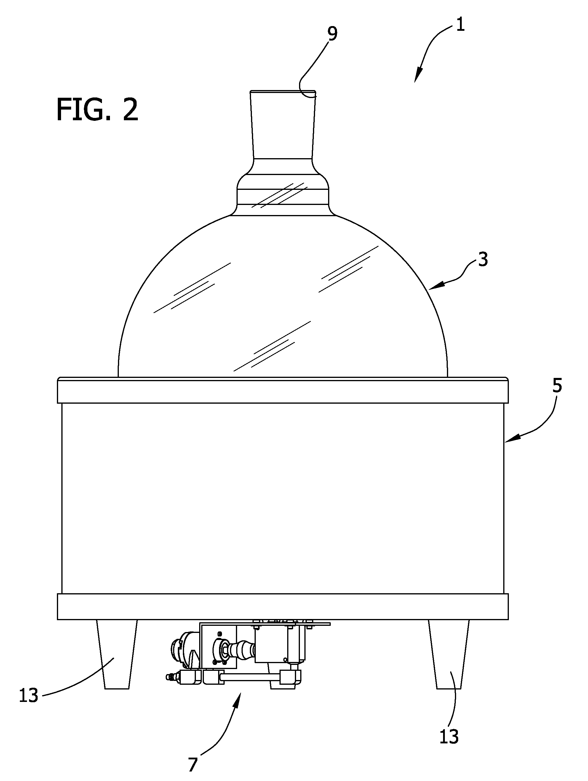
[0018]Referring now to the drawings, and particularly to FIGS. 1-4, a magnetic stirring system of the invention is shown generally at 1. The magnetic stirring system 1 generally includes a flask 3 (broadly, a “vessel”), a stir-mantle 5 shaped to support the flask within the stir-mantle, and a magnetic stirring apparatus 7 mounted to an underside of the stir mantle 5. These components are indicated generally by their reference numbers. The illustrated flask 3 is generally spherical in shape and includes a small inlet opening 9 toward its top for introducing materials (not shown, but which may include, for example, materials used in a distillation process, highly volatile materials, explosive materials, or other materials that may ignite around sparks) into the flask 3 and for substantially preventing release of materials from the flask into the environment or vice versa. Additional openings may be present in the flask 3 to attach other components not described herein that may be used...


PUM


Abstract

A magnetic stirring system includes a stir-mantle and a magnetic stirring apparatus used for stirring / mixing materials in a flask. A rare-earth magnet is mounted on the magnetic stirring apparatus and is driven in rotation by a pneumatic motor. The rare-earth magnet is coupled to a magnetic stir bar in the flask for conjoint rotation so that the stir-bar stirs / mixes the materials in the flask. An exhaust is included to channel air from the motor to the rare-earth magnet and to direct the air to flow over the magnet to control the temperature of the magnet.

Description

FIELD OF THE INVENTION[0001]The present invention relates generally to stirrers, and more particularly to a magnetic stirrer for mixing material within a vessel.BACKGROUND OF THE INVENTION[0002]Many chemical reactions and physical reactions (e. g., distillations) are facilitated by stirring / mixing the materials within a vessel. One way to do this is to stir the materials in a vessel with a mechanical stirrer. For example, a motor-driven rotatable spindle may be used in which one or more stirring members (e.g., blades) of the spindle can be positioned in the vessel to stir the materials.[0003]As another example, a motor-driven magnetic stirrer may be used. In this stirrer, a magnetic stir bar is positioned within the vessel and a base magnet magnetically coupled to the stir bar is positioned under the vessel near the stir bar. A motor is used to rotate the base magnet, which in turn rotates the stir bar in the vessel to stir the materials. A magnetic stirrer is often desirable becaus...

Claims


Application Information

Patent Timeline
Patent Type & Authority Applications(United States)
IPC IPC(8): B01F13/08B01F15/06
CPCB01F15/005B01F13/0818B01F33/452B01F35/32015
Inventor ANDREWS, BRYAN C.DETWILER, DARRYL B.
Owner SIGMA ALDRICH CO LLC
Why Eureka
Try Eureka