Bicycle Pump

a technology of bicycles and pumping devices, which is applied in the direction of pump components, positive displacement liquid engines, liquid fuel engine components, etc., can solve the problems of user holding and attaching to the frame, and achieve the effect of carrying out the pumping operation conveniently and effectively restraining in pla

Inactive Publication Date: 2008-01-17
WU NA
View PDF15 Cites 8 Cited by
  • Summary
  • Abstract
  • Description
  • Claims
  • Application Information

AI Technical Summary

Benefits of technology

[0011] A base is attached to the cylindrical body and includes a footstand on which the user can step to anchor the bicycle pump for a stable pumping action. The base also includes a hose connected thereto. In addition, the hose is configured to have a length that is about twice as long as the cylindrical body for allowing the user to carry out the pumping operation conveniently, either with or without anchoring the bicycle pump to the ground. Furthermore, the hose is adapted be hanged by the hooking element at about the middle of its length and is adapted to be receivable by the second clipping portion.
[0012] It is an objective of this invention that it allows the user to carry out the pumping operation conveniently, either with or without anchoring the bicycle pump to the ground.
[0013] It is another objective of this invention that the hose is effectively restrained in place on the bicycle pump.

Problems solved by technology

However, the problem of the floor pump is that it is difficult to be attached to the frame of the bicycle and the drawback of the frame pump is that it requires the user to hold and stabilize the body of the pump with one hand while the other hand carries out the pumping action all the time.

Method used


Image

  • Bicycle Pump
  • Bicycle Pump
  • Bicycle Pump

Examples


Embodiment Construction

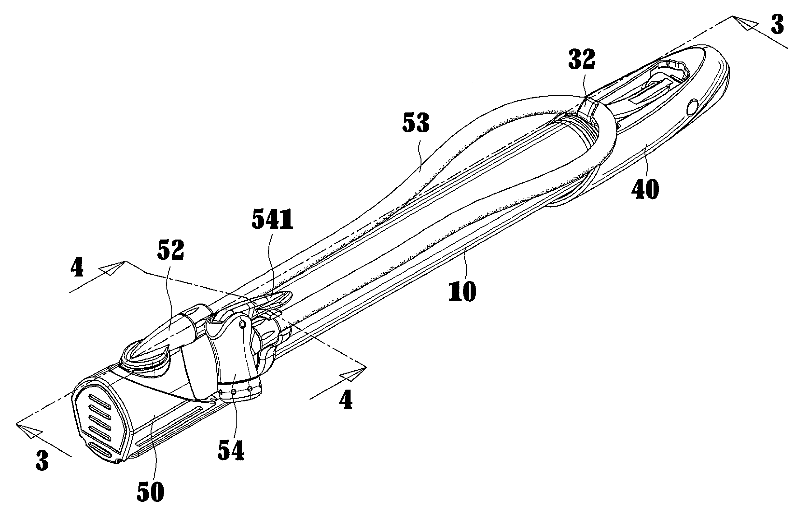
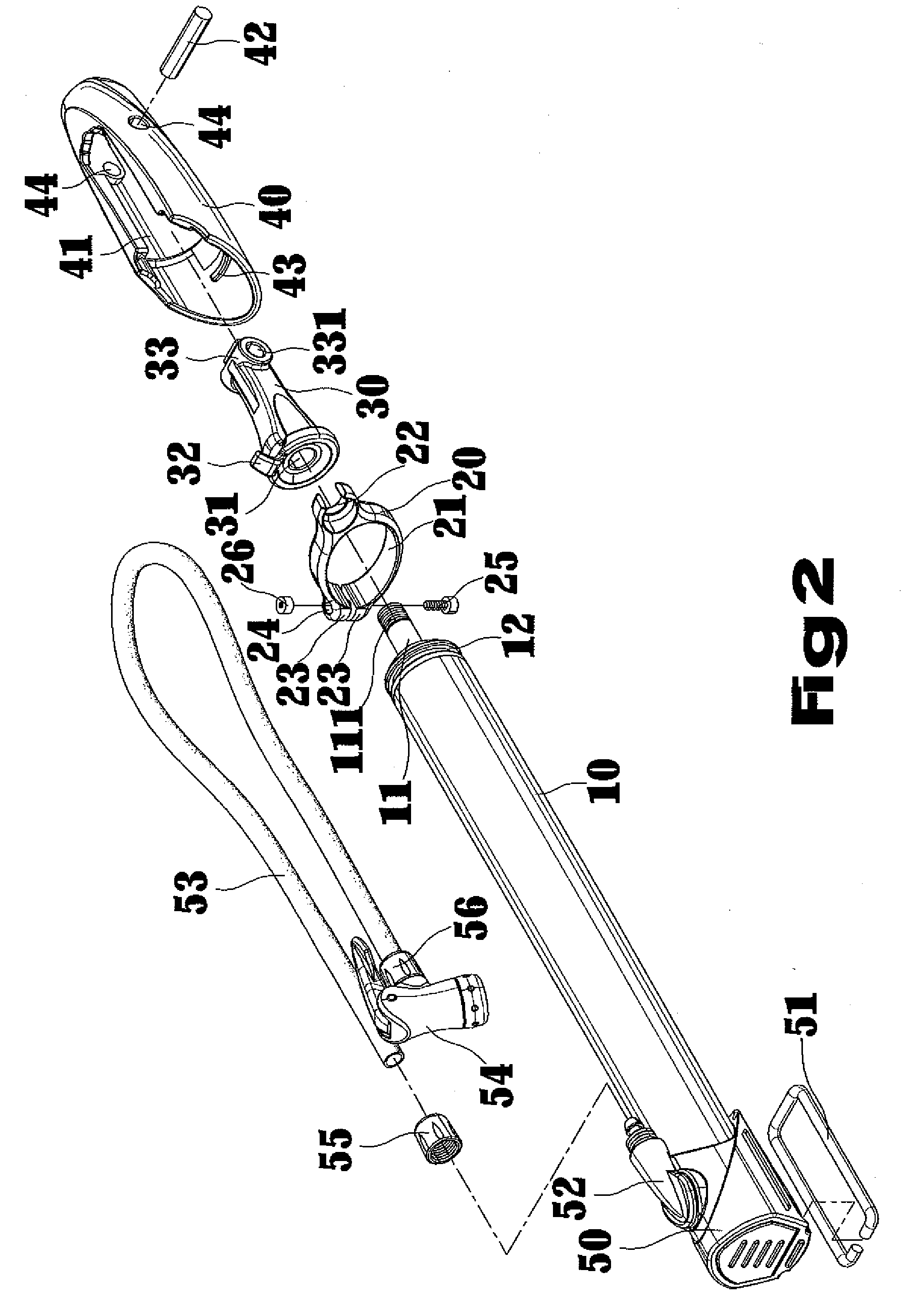
[0021] Referring to FIGS. 1 though 4, a bicycle pump includes a cylindrical body 10 in which a rod 11 disposes. The cylindrical body 10 includes a first end having an indentation 12 disposed about the outer peripheral surface of the cylindrical body 10 and a second end to which a base 50 attaches. The rod 11 is moveable inside the cylindrical body 10 and includes a portion exposed outside the first end of the cylindrical body 10. In addition, the portion has a threaded section 111 formed thereon for engaging with a head 30, which will be described further below.

[0022] A clip 20 is attached to the outer peripheral surface of the cylindrical body 10. The clip 20 includes a first clipping portion 21 which is adapted for insertion of the cylindrical body 10. In this embodiment, the clip 20 is disposed adjacent to where the base 50 is installed. The clip 20 also includes a pair of protrusions 23 parallel to and spaced apart from each other. Each protrusion 23 has a stepped fastening hol...


PUM


Abstract

A bicycle pump includes a cylindrical body in which a rod disposes. The rod is moveable inside the cylindrical body. A clip is attached to the outer peripheral surface of the cylindrical body. The clip includes a first clipping portion provided to allow insertion of the cylindrical body. The clip also has a second clipping portion defined on the periphery of the first clipping portion. A head is connected to the rod. The head also includes a hooking element thereon. A handle is pivotally connected to the head. A base is attached to the cylindrical body and includes a footstand on which the user can step to anchor the bicycle pump. The base also includes a hose. The hose has a length that is about twice as long as the cylindrical body. The hose is adapted be hanged by the hooking element and receivable by the second clipping portion.

Description

CROSS REFERENCE [0001] The present application is a continuation-in-part application of U.S. patent application Ser. No. 11 / 039,726, filed on Jan. 19, 2005, of which the entire disclosure is incorporated herein.BACKGROUND OF THE INVENTION [0002] 1. Field of the Invention [0003] The present invention relates to bicycle pumps. [0004] 2. Description of the Related Art [0005] Most known hand operated bicycle pumps fall into one of the two classes; floor pumps in which the body of the pump rests upon a ground, the pump generally has a footpeg on which the user can step to anchor the body of the pump for a stable pumping action. The floor pump also includes a hose that gives the user a greater margin of distance from the bicycle to thereby facilitate pumping operation; and frame pumps in which the body of the pump is light, and compact, so that the pump is portable and easily attachable to the bicycle frame. However, the problem of the floor pump is that it is difficult to be attached to ...

Claims


Application Information

Patent Timeline
Patent Type & Authority Applications(United States)
IPC IPC(8): F04B53/00
CPCF04B33/005
Inventor WU, SCOTT
Owner WU NA
Why Eureka
Try Eureka