
Method And System For Spurious Signal Control In Receivers

a technology of spurious signal and receiver, applied in the direction of transmission, sinusoidal oscillation interference reduction, electric apparatus, etc., can solve problems such as unwanted rf tone, and achieve the effect of reducing or eliminating blocker signals

Active Publication Date: 2008-01-17
ICERA CANADA ULC
View PDF10 Cites 16 Cited by
  • Summary
  • Abstract
  • Description
  • Claims
  • Application Information

AI Technical Summary

Benefits of technology

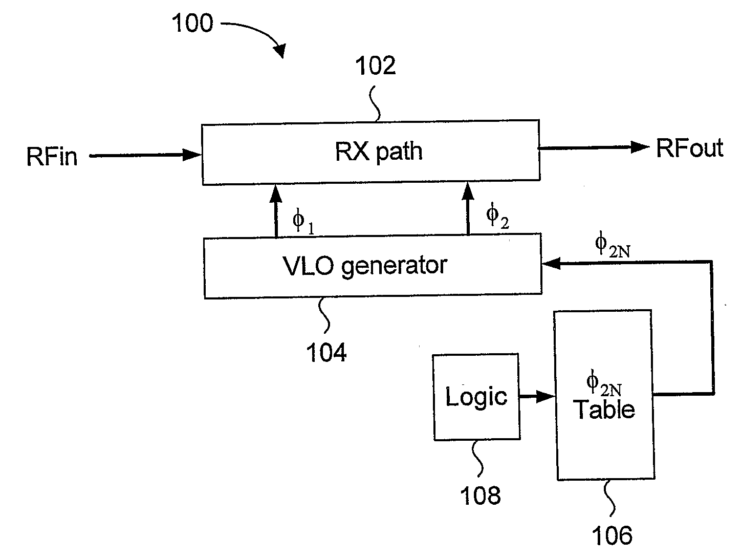
"The present invention provides a blocking signal reduction system for a virtual local oscillator receiver. The system includes a synthesizer circuit, evaluation means, and a dynamic correction circuit. The evaluation means can detect the presence of a blocking signal and adjust the second mixer signal to reduce the unwanted signal. The dynamic correction circuit can sense the power of the base band signal and adjust the second mixer signal to match the power of the first mixer signal. This results in an effective local oscillator signal that does not overlap with the desired signal. The system can also include a blocker detection circuit and a memory to store preselected frequency values for specific channels and standards. The method can detect the blocking signal by measuring the power of the RF input signal and comparing it to a predetermined threshold. The invention aims to improve the blocking signal reduction in a virtual local oscillator receiver."

Problems solved by technology

This results in an unwanted RF tone that does not overlap with a wanted signal at the desired frequency.

Method used


Image

  • Method And System For Spurious Signal Control In Receivers
  • Method And System For Spurious Signal Control In Receivers
  • Method And System For Spurious Signal Control In Receivers

Examples


Embodiment Construction

[0038] Generally, the present invention provides a method and system for dynamically shifting spurious tones away from the desired frequency in a virtual local oscillator receiver, such that any undesired signal residing at such spurious tones are effectively delineated from the desired signal and removed from the RF input signal. The system detects the presence of potential undesired blocker signals in the RF input signal, and initiates an iterative power comparison and mixer signal adjustment loop. As the virtual local oscillator uses two mixer signals, the frequency of one of the mixer signals is adjusted during the loop until the power of the down-converted signal is minimized to a predetermined level. Minimized power in the down-converted signal is indicative of the absence of the blocker signal, since the presence of a relatively high power signal is indicative of a blocker signal overlapping with a desired signal.

[0039] The embodiments of the present invention take advantage...


PUM


Abstract

A method and system for dynamically shifting spurious tones away from the desired frequency in a virtual local oscillator receiver, such that any undesired signal residing at such spurious tones are effectively delineated from the desired signal and removed from the RF input signal. The system detects the presence of potential undesired blocker signals in the RF input signal, and initiates an iterative power comparison and mixer signal adjustment loop. As the virtual local oscillator uses two mixer signals, the frequency of one of the mixer signals is adjusted during the loop until the power of the down-converted signal is minimized to a predetermined level. Minimized power in the down-converted signal is indicative of the absence of the blocker signal, since the presence of a relatively high power signal is indicative of a blocker signal overlapping with a desired signal.

Description

FIELD OF THE INVENTION [0001] The present invention relates generally to communications, and to down-conversion of an RF signal to a lower frequency in a radio. More specifically, the present invention relates to management of spurious components generated by the radio. BACKGROUND OF THE INVENTION [0002] Many communication systems up-convert electromagnetic signals from base band to higher frequencies for transmission, and subsequently down-convert those high frequencies back to their original frequency band when they reach the receiver, processes known as up-conversion and down-conversion (or modulation and demodulation) respectively. The original (or base band) signal, may be, for example, data, voice or video. These base band signals may be produced by transducers such as microphones or video cameras, be computer generated, or transferred from an electronic storage device. In general, the high frequencies provide longer range and higher capacity channels than base band signals, a...

Claims


Application Information

Patent Timeline
Patent Type & Authority Applications(United States)
IPC IPC(8): H04B1/26H03D7/00H04B1/30H04B15/06
CPCH03D7/00H04B2215/065H04B15/06H04B1/30
Inventor MANKU, TAJINDERKAHRIZI, MASOUD
Owner ICERA CANADA ULC
Learn More