
Method for accessing a sinus cavity and related anatomical features

a sinus cavity and anatomical feature technology, applied in the field of sinusitis treatment or amelioration devices and methods, can solve the problems of significant post-operative pain for patients, relative invasive procedure to the nasal cavity and sinuses, and the subsequent removal of the packing can be quite painful

Active Publication Date: 2008-01-17
ENTELLUS MEDICAL
View PDF84 Cites 195 Cited by
  • Summary
  • Abstract
  • Description
  • Claims
  • Application Information

AI Technical Summary

Benefits of technology

This approach provides a less invasive means to expand constricted sinus passageways, potentially reducing pain and complications associated with traditional surgeries, and can be more accessible and cost-effective for patients, while effectively addressing sinusitis by improving mucous drainage.

Problems solved by technology

While this procedure is generally effective, it is a relatively invasive procedure to the nasal cavity and sinuses.
There can be significant post-operative pain for the patient, and sometimes there are bleeding complications that require packing to be placed in the nasal cavity.
Subsequent removal of this packing can be quite painful.
Also, since the nasal and sinus tissue are significantly traumatized, it may take several days to weeks to know whether the surgery was successful.
This is especially true if various healing agents such as MeroGel® (Medtronic / Xomed) were placed at the surgical site, as these often block the sinus drainage until they are flushed away or degrade away after several days.
Additionally, in certain patients, the ostial regions of the surgically-treated sinuses can become re-obstructed with excess growth of scar tissue as a result of the tissue trauma.
When the advantages and disadvantages of the surgery are considered for a patient with sinusitis, there are many patients in whom the surgery may not be appropriate.
For example, their condition may not be considered “chronic enough” or extensive enough to warrant FESS surgery.
In other situations, the patient may be fearful of the pain or other aspects of having FESS performed.
Alternatively, the FESS procedure may be too costly for a particular patient.

Method used


Image

  • Method for accessing a sinus cavity and related anatomical features
  • Method for accessing a sinus cavity and related anatomical features
  • Method for accessing a sinus cavity and related anatomical features

Examples


Embodiment Construction

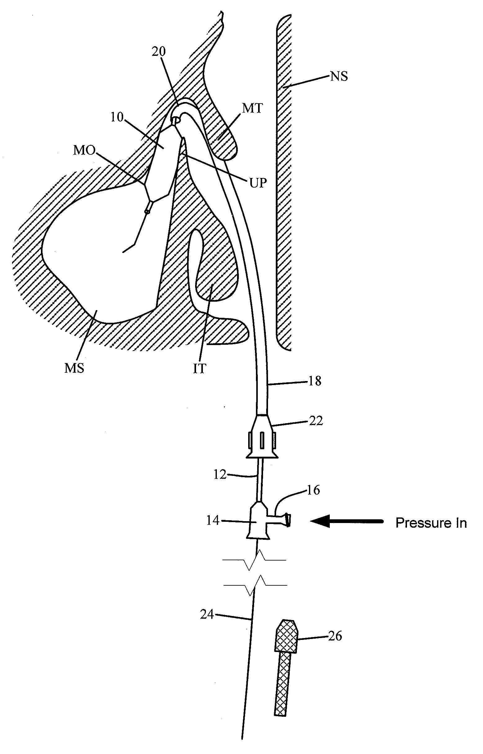
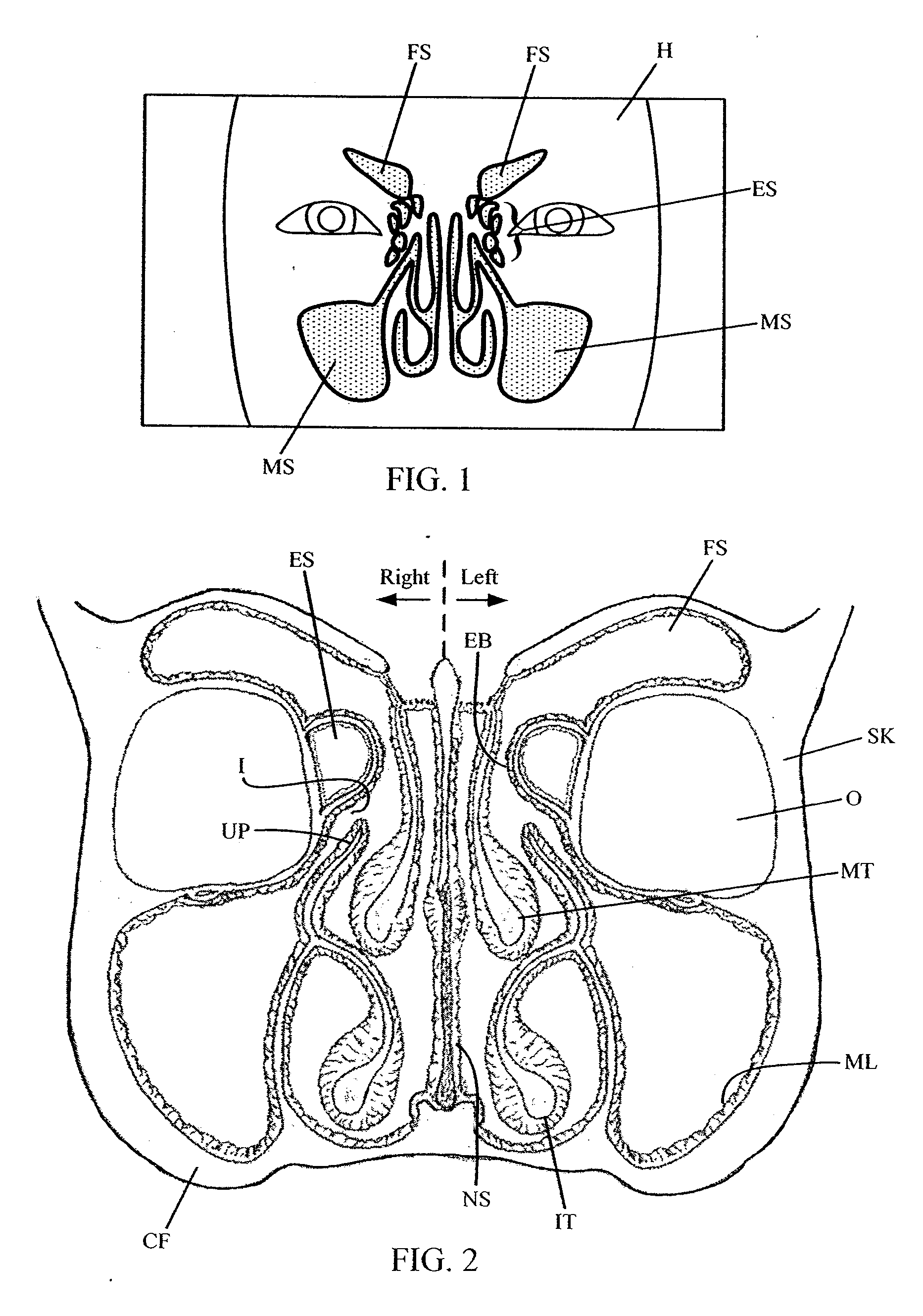
[0093]FIG. 1 illustrates a frontal anatomical representation (parallel to the coronal plane) showing the sinuses FS, ES, MS located within a patient's head H. Above and behind the eyebrows are the frontal sinuses FS. Between the eyes are the ethmoid sinuses ES. Note that unlike the other sinuses, the ethmoids are typically formed as a “honeycombed” structure consisting of several individual air cells. Located behind the cheeks are the maxillary sinuses MS. The sphenoid sinuses are not shown in FIG. 1, but are located further posterior to the ethmoid sinuses.

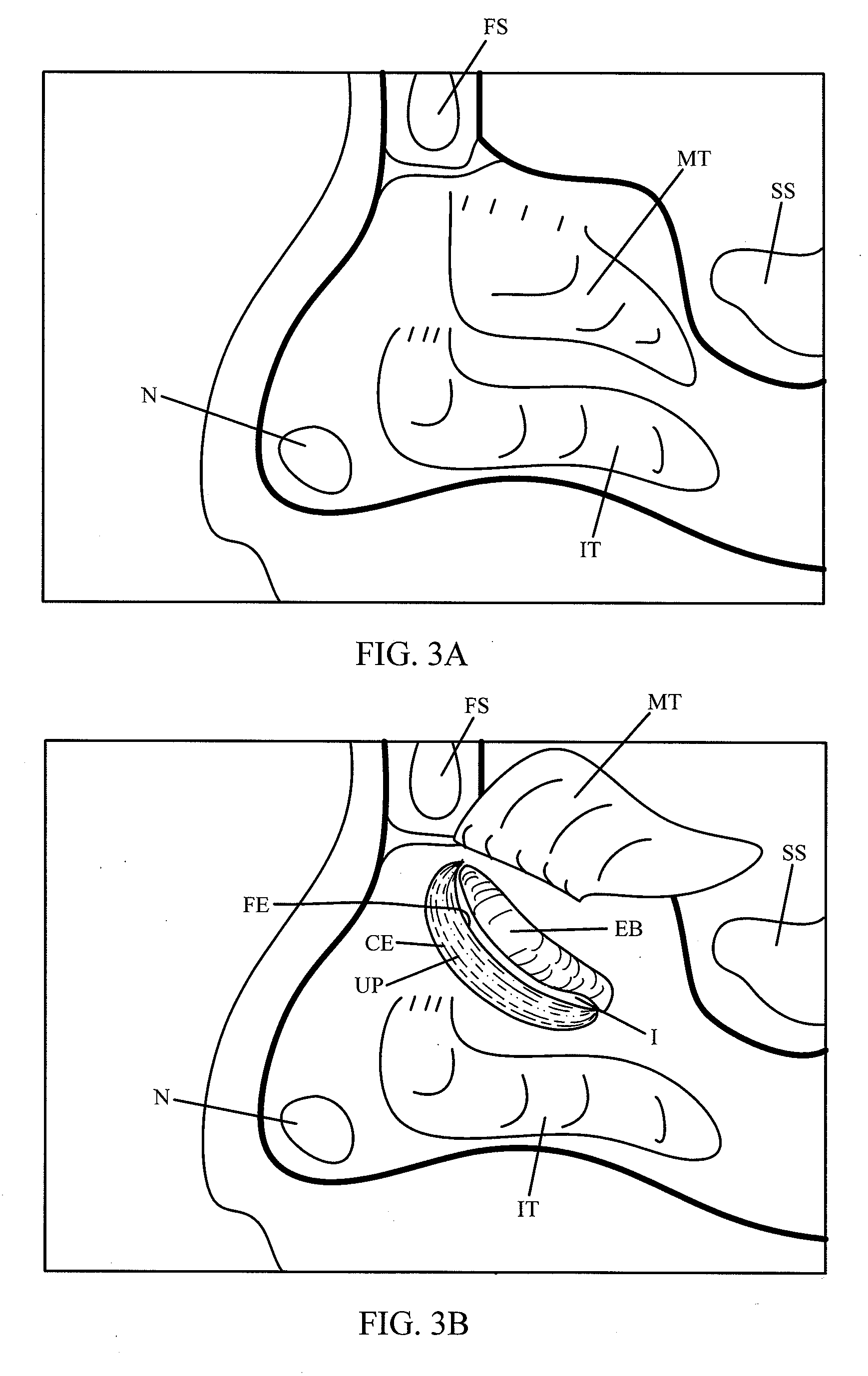
[0094]FIG. 2 is another frontal view of the sinuses located within the skull bone SK showing additional features. The nasal septum NS divides the nasal cavity into left and right sides. Because the following described structures are generally symmetrical bilaterally, only one of the paired structures is illustrated for sake of convenience. Within the nasal cavity are the middle turbinate MT and the inferior turbinate IT. The mid...


PUM


Abstract

A method of confirming the location of an elongate member configured for placement within a patient's sinus cavity comprises introducing the elongate member through a nasal passageway to place a distal tip of the elongate member in a test position, the elongate member configured to emit illuminating light via the distal end of the elongate member. The location of the light is then viewed through the patient's skin to confirm the positioning of the elongate member.

Description

RELATED APPLICATIONS [0001] This application is a continuation of U.S. application Ser. No. 11 / 379,691 filed on Apr. 21, 2006. Priority is claimed pursuant to 35 U.S.C. § 120 and all other applicable statutes. The '691 application is incorporated by reference as if set forth fully herein.FIELD OF THE INVENTION [0002] The field of the invention generally relates to devices and methods for the treatment or amelioration of sinusitis. BACKGROUND OF THE INVENTION [0003] Sinusitis is a condition affecting over 35 million Americans, and similarly large populations in the rest of the developed world. Sinusitis occurs when one or more of the four paired sinus cavities (i.e., maxillary, ethmoid, frontal, sphenoid) becomes obstructed. These paired cavities are located in the skull behind the face, as is depicted in FIGS. 1, 2, and 3A. Normally the sinus cavities, each of which are lined by mucosa, produce mucous which is then moved by beating cilia from the sinus cavity out to the nasal cavity...

Claims


Application Information

Patent Timeline
Patent Type & Authority Applications(United States)
IPC IPC(8): A61M25/10A61F2/958
CPCA61B17/12022A61B17/12104A61B17/12136A61B17/24A61B17/3421A61B17/3468A61M29/02A61B19/5202A61B2017/1205A61B2019/5445A61F2/82A61M2210/0618A61M2210/0681A61B19/26A61B2090/3945A61B90/30A61B90/50A61M2029/025
Inventor KEITH, PETER T.RESSEMANN, THOMAS V.TRUITT, THEODORE O.
Owner ENTELLUS MEDICAL
Learn More