Aircraft extremity marker

a technology of extremity marker and aircraft, which is applied in the field of marks, can solve the problems of difficult to judge the location of extremities, affecting the accuracy of the position of extremities, and being subject to extremities

Active Publication Date: 2008-01-24
MOORE MICHAEL
View PDF19 Cites 2 Cited by
  • Summary
  • Abstract
  • Description
  • Claims
  • Application Information

AI Technical Summary

Benefits of technology

[0005]An object of the invention is to provide a marker for an aircraft extremity, such as a wingtip, to make the aircraft extremity more visible so that a person moving the ai

Problems solved by technology

Aircraft, while parked, or when taxiing or being towed from one ground location to another, are subject to having their extremities, such as wingtips, collide with another object.
Even in small private aircraft, the wings are long and the person moving the aircraft is not normally close to the wingtips,

Method used


Image

  • Aircraft extremity marker
  • Aircraft extremity marker
  • Aircraft extremity marker

Examples


Embodiment Construction

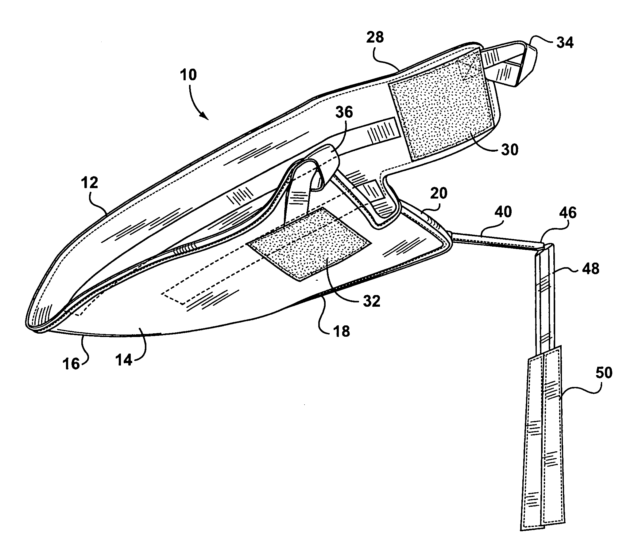
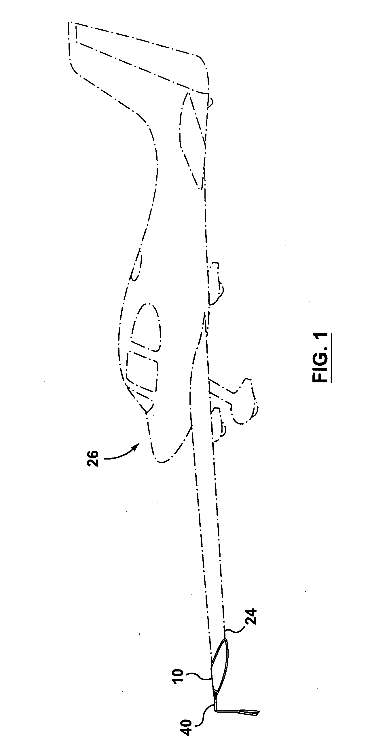
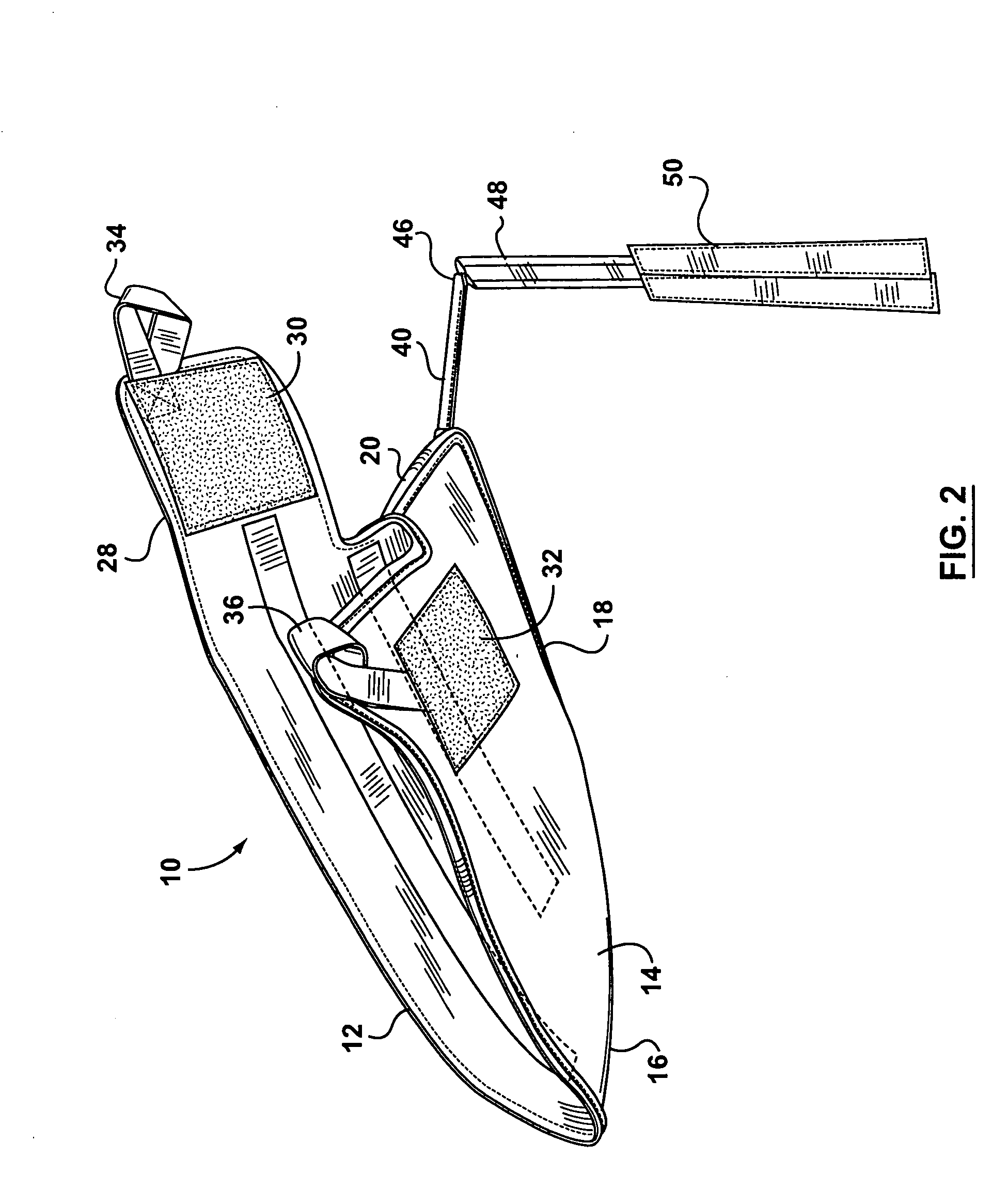
[0025]Reference is first made to FIGS. 1 to 6, which show a preferred embodiment of the invention. As shown, there is provided a wingtip marker 10, typically formed from a woven solution dyed, acrylic fiber or ballistic nylon with a polyurethane coating. (Other suitable materials may also be used.) The marker 10 includes an upper layer 12 and a lower layer 14 sewn together along three edges 16, 18, 20 to form a type of pouch or open-ended envelope adapted to slide onto the wingtip 24 of an aircraft 26. The marker 10 includes a flap 28 extending from one edge thereof, as best shown in FIG. 2. The inside or lower surface of the flap 28 is covered with a patch 30 of a hook and loop fastener (such as that sold under the trade-mark VELCRO) attached thereto (by sewing or by adhesive or both). After the marker 10 is pulled tightly onto an aircraft wingtip, the flap 28 is folded over a complementary hook and loop fastener patch 32 fastened to the lower surface of the lower layer 14. The pat...


PUM


Abstract

A marker for the wingtip or other extremity of an aircraft. The marker includes a fabric pouch having a flap containing hook and loop fasteners, to hold the pouch on the aircraft extremity. A fabric tube extends outwardly and substantially horizontally from the pouch and supports a marker flag at its tip. The fabric tube contains a breakable support rod, so that if the aircraft wingtip collides with an object, the support rod will break and the flag will droop, providing a visible indication that a collision has occurred. The broken rod can then be replaced.

Description

FIELD OF THE INVENTION [0001]This invention relates to an improved marker for making an aircraft extremity (such as a wingtip) more visible and for providing a visible indication if a collision has occurred between the aircraft extremity and another object.BACKGROUND OF THE INVENTION [0002]Aircraft, while parked, or when taxiing or being towed from one ground location to another, are subject to having their extremities, such as wingtips, collide with another object. Even in small private aircraft, the wings are long and the person moving the aircraft is not normally close to the wingtips, nor to the elevators or rudder, so it is difficult to judge their locations. It is therefore all too common to have collisions between the extremities of one aircraft and those of another on the ground. It is also common to have collisions for example between aircraft wingtips and the edges of hanger door openings or other objects in the hanger. The damage caused by these collisions is not always e...

Claims


Application Information

Patent Timeline
IPC IPC(8): G08B5/02
CPCB64F1/005
Inventor MOORE, MICHAEL
Owner MOORE MICHAEL
Why Eureka
Try Eureka