Method of Forming Partition Assembly Having Floor Parent Welded to Partitions

a technology of partition assembly and parent wall, which is applied in the field of partition assembly, can solve the problems of affecting the quality of products or parts, the upper edge of the partition may have exposed sharp edges, and the contents of the container from contacting one another,

Inactive Publication Date: 2008-01-24
BRADFORD CO
View PDF25 Cites 6 Cited by
  • Summary
  • Abstract
  • Description
  • Claims
  • Application Information

AI Technical Summary

Benefits of technology

[0016] In one embodiment of the present invention, the partition is formed of a multilayered material folded in half and secured to itself. The fold creates a rounded upper edge at the fold line which is smooth and has a continuous surface with the outer side walls or skins of the partition. The partition blank comprises an inner layer of foam, preferably polyolefin foam, and an outer layer, skin or facegood. In one embodiment, the inner foam layer is bonded directly or laminated to the outer layer. The outer layer may be made of woven polyester, non-woven polypropylene, foamed or solid polyolefin or other material such as latex or non-polyolefin plastic. The outer layer may be selected as appropriate to protect or prevent surface damage to the products being stored and / or shipped in the cells of the container.
[0036] This method of securing a floor to a partition assembly is quick, easy and inexpensive. The intersecting first and second slotted partitions are permanently secured to each other along one edge, making the assembly non-disassembling and also enhanced by a bottom or floor permanently attached to one edge of the partition assembly without using any additional material or tools.

Problems solved by technology

However, the dividers may be constructed of any suitable material with sufficient rigidity to prevent the contents of the container from contacting one another and being damaged.
One disadvantage with known partition assemblies is that the upper edges of the partitions may have exposed sharp edges.
Such an exposed upper edge of the partition may damage products or parts being loaded into or unloaded from the cells of the container in which is located the partition matrix or assembly.
Another disadvantage of such partition assemblies is that the person loading or unloading parts or products into or from the cells of the container may cut or scrape their knuckles or hands on the exposed upper edges of the partitions when loading or unloading parts or products.
Consequently, the partitions may contact the products or parts stored in the cells and damage them.
Additionally, the partition plies may easily tear or otherwise be damaged.
Upon assembly or disassembly of the partition matrix, one or more portions of the partitions may tear and hence cause disassembly of at least a portion of the partition matrix.
Additionally, it may be difficult to parent weld partitions made partially or entirely of foam to a plastic supporting net.

Method used


Image

  • Method of Forming Partition Assembly Having Floor Parent Welded to Partitions
  • Method of Forming Partition Assembly Having Floor Parent Welded to Partitions
  • Method of Forming Partition Assembly Having Floor Parent Welded to Partitions

Examples


Embodiment Construction

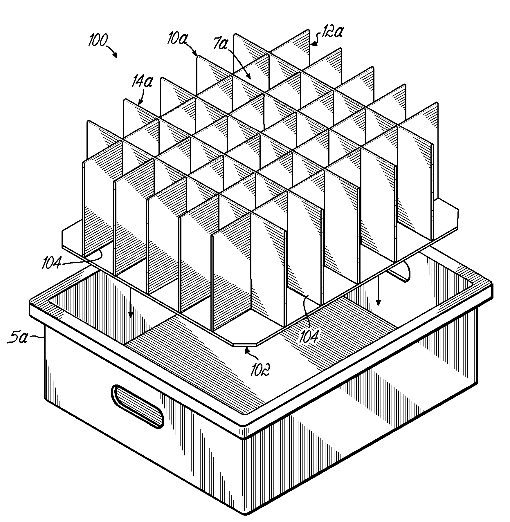
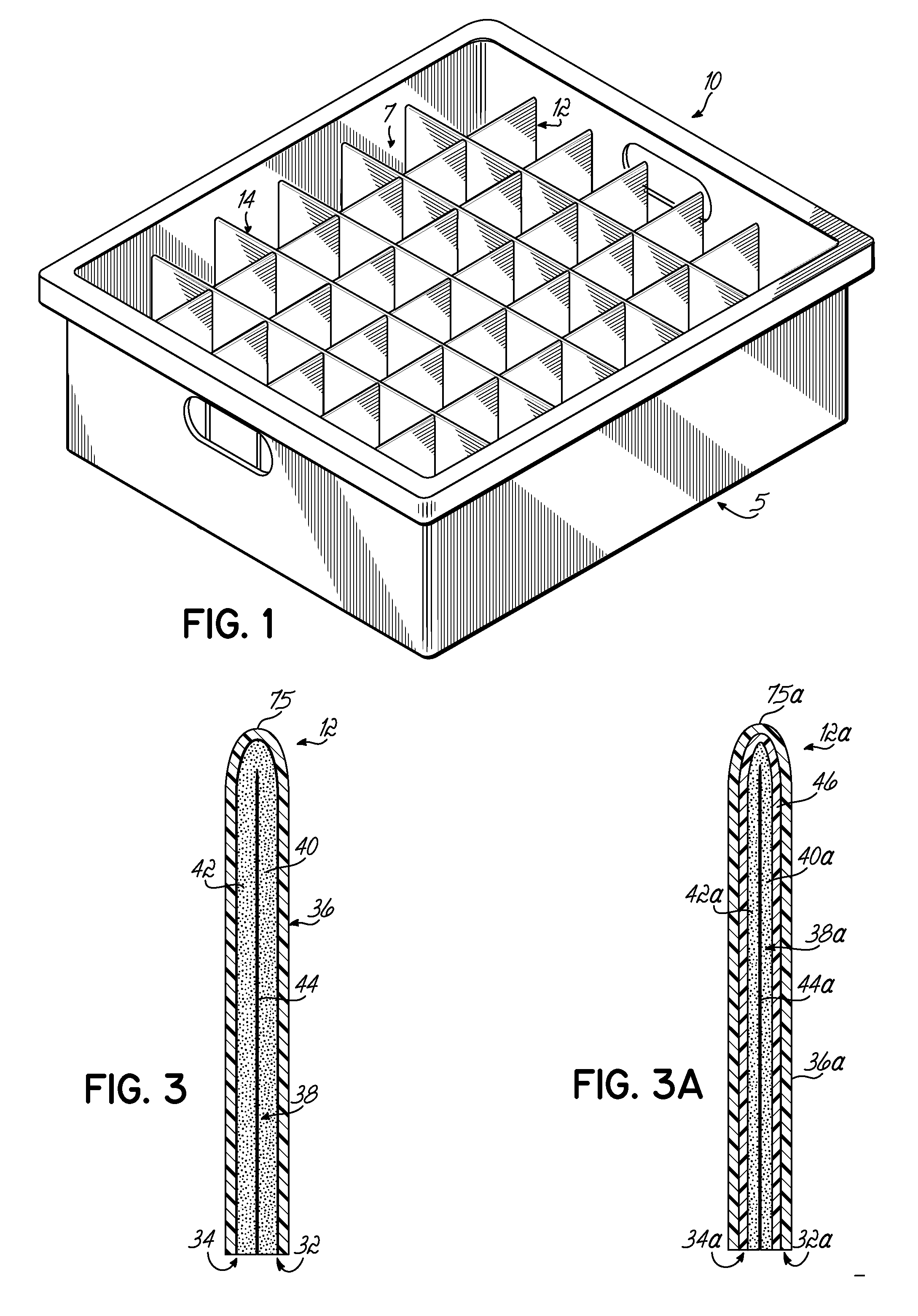
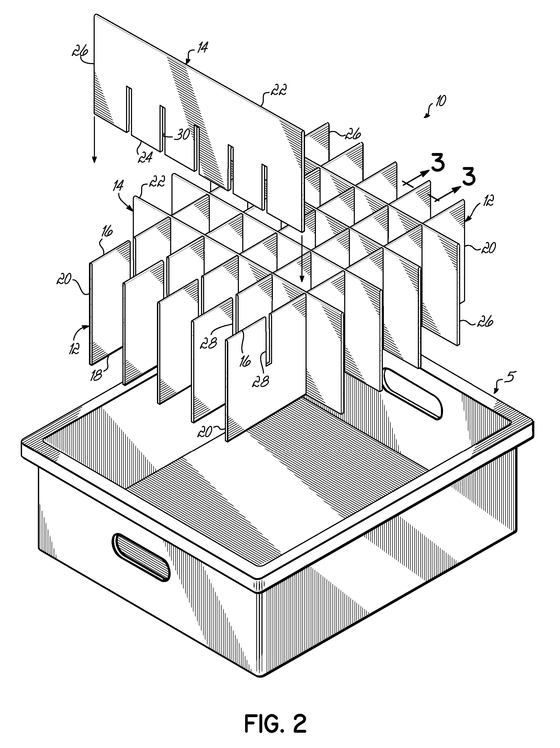
[0065] Referring to the drawings and particularly to FIG. 1, there is illustrated a partition assembly 10 for dividing the space inside a container 5. Although one type or configuration of container 5 is illustrated in FIG. 1, the partition assembly 10 of the present invention may be used in any type of container or box. As illustrated in FIG. 2, the partition assembly 10 comprises a plurality of parallel first slotted partitions 12 intersecting with a plurality of parallel second slotted partitions 14.

[0066] As shown in FIG. 2, each first slotted partition 12 has a rounded upper or top edge 16, a planar bottom edge 18 and two opposed side edges 20. Likewise each second slotted partition 14 has a rounded upper or top edge 22, a planar bottom edge 24 and two opposed side edges 26.

[0067] Each first slotted partition 12 has at least one slot 28 which extends downwardly from the top edge 16 of the first slotted partition 12 to approximately the midpoint of the first slotted partition ...


PUM

PropertyMeasurementUnit
lengthaaaaaaaaaa
rigidityaaaaaaaaaa
sizeaaaaaaaaaa

Abstract

A method of manufacturing a non-disassembling partition assembly (100) comprises providing a partition matrix (10a) made up of intersecting first and second slotted partitions (12a, 14a). The partitions (12a, 14a) may be made by folding over a partition blank (66) and securing a foam portion (38) of the folded partition blank (66) to itself. The foam (38) may be heated before being cooled under pressure to secure opposed plies (32,34) of the partition together. The partition assembly (100) is held together by a floor (102) parent welded to the intersecting partitions (12a, 14a). The floor (102) has a lower outer skin (108) and a foam layer (106) to which the partitions (12a, 14a) are parent welded.

Description

CROSS-REFERENCE TO RELATED APPLICATIONS [0001] This application is a divisional of U.S. patent application Ser. No. 11 / 183,538 filed Jul. 18, 2005 entitled “Partition Assembly Having Floor Parent Welded to Partitions”, which is fully incorporated by reference herein. U.S. patent application Ser. No. 11 / 183,538 is a Continuation-in-Part of U.S. patent application Ser. No. 11 / 036,809 filed Jan. 14, 2005 entitled “Partition Assembly Made With Multiple Ply Partitions”, which is also fully incorporated by reference herein.FIELD OF THE INVENTION [0002] The present invention relates to a partition assembly for dividing the space inside a container or box; more particularly to a partition assembly made of slotted, multiple ply partitions. DESCRIPTION OF THE PRIOR ART [0003] In the storage, shipment or display of parts or merchandise, it is a common practice to divide the interior of a box or container into a plurality of individual cells. The interior of a box or container is typically sepa...

Claims


Application Information

Patent Timeline
Patent Type & Authority Applications(United States)
IPC IPC(8): B29C65/00
CPCB29C47/0019B29C66/542B29C47/0042B29C47/0066B29C53/36B29C65/103B29C65/1432B29C65/18B29C65/20B29C65/48B29C65/56B29C66/024B29C66/0242B29C66/0342B29C66/45B29C66/727B29C66/80B29C66/83413B29C69/001B29C2793/00B29K2023/00B29K2023/12B29K2067/00B29K2105/0064B29K2105/04B29K2105/0845B29K2105/0854B29L2009/00B29L2024/006B29L2031/712B31B11/00B31B2217/103B31D1/0043B31D5/0004B32B37/06B32B37/08B32B37/203B32B2305/022B65D5/4803B65D5/48038B65D25/04B29C47/0038B29C66/8181B29C47/065B29C66/83221B29C66/114B29C66/1122B29C66/112B29C66/1142B29C65/00B29C66/12441B29C66/71B29C66/723B31B50/81B31B2105/00B31B2120/20B29C48/001B29C48/0012B29C48/0022B29C48/07B29C48/21B29K2023/10
Inventor BRADFORD, JUDSON A.NYEBOER, CALVIN D.FEENSTRA, MARK J.
Owner BRADFORD CO
Why Eureka
Try Eureka