

Flat miniaturized antenna of a wireless communication device
a wireless communication device and miniaturized antenna technology, applied in the structural form of radiating elements, elongated active elements, resonance antennas, etc., can solve the problems of low efficiency, low power, low quality factor, hidden antennas,
- Summary
- Abstract
- Description
- Claims
- Application Information
AI Technical Summary
Problems solved by technology
Method used
Image

Examples
first embodiment
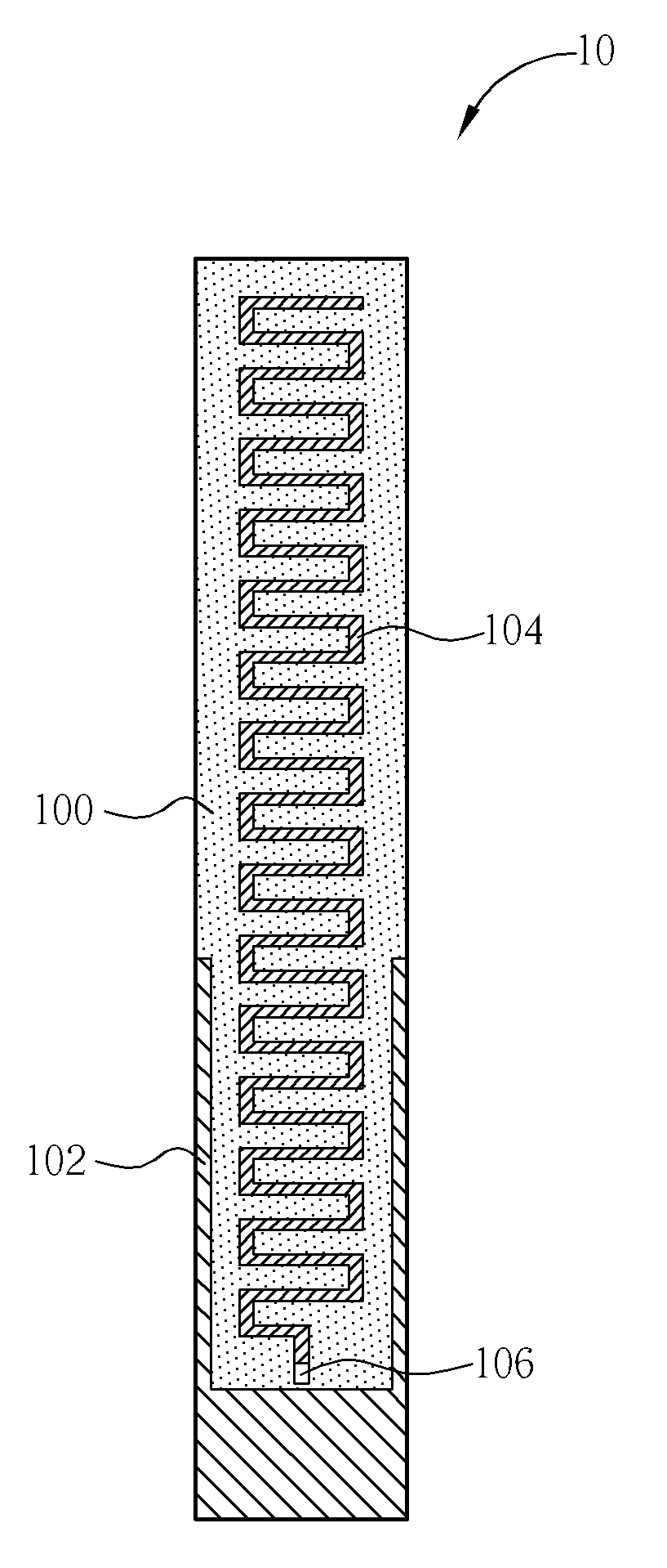
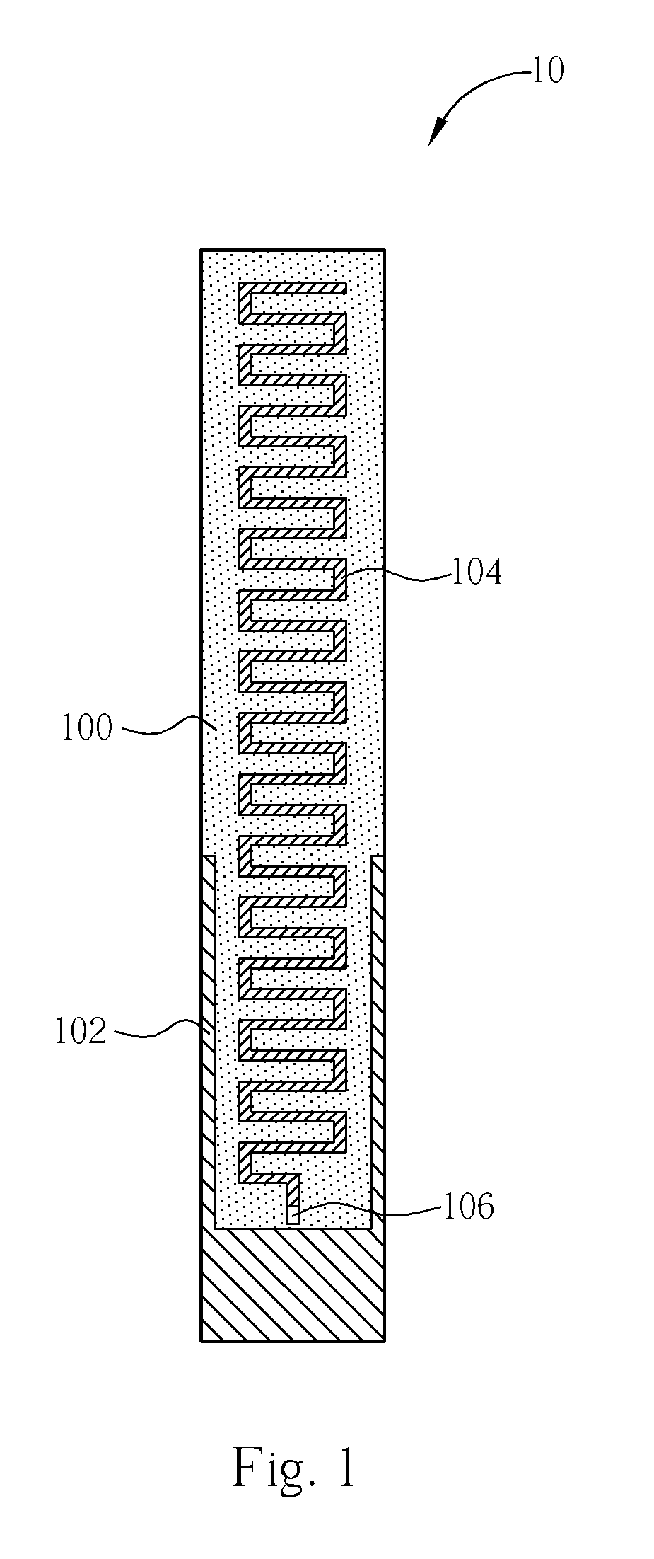
[0021]Please refer to FIG. 1. FIG. 1 is a diagram of a flat miniaturized antenna 10 of a wireless communication device according to the present invention. The flat miniaturized antenna 10 comprises a baseboard 100, a sleeve conductor 102, a meander-shaped conductor 104, and a feed-in end 106. The baseboard 100 is made of a dielectric material or a magnetic material for disposing conductors made of copper foils or other materials. The sleeve conductor 102 is formed on the baseboard 100 and is coupled to system ground (not shown in FIG. 1). The shape of the sleeve conductor 102 is like a sleeve. The meander-shaped conductor 104 stretches outward from the cuff of the sleeve conductor 102 in a reciprocating bent manner for forming the radiator of the flat miniaturized antenna 10. The feed-in end 106 is formed on an end of the meander-shaped conductor 104 close to the sleeve conductor 102 for transmitting wireless signals received by the meander-shaped conductor 104 to the wireless commu...
second embodiment
[0024]Please refer to FIG. 4. FIG. 4 is a diagram of a flat miniaturized antenna 40 of a wireless communication device according to the present invention. The flat miniaturized antenna 40 comprises a baseboard 400, a meander-shaped conductor 404, and a feed-in end 406. The baseboard 400 is made of a dielectric material or a magnetic material for disposing conductors made of copper foils or other materials. The meander-shaped conductor 404 is formed on the baseboard 400 in a reciprocating bent manner. The meander-shaped conductor 404 has a wide end and a narrow end. The feed-in end 406 is formed on the wide end of the meander-shaped conductor 404 for transmitting wireless signals received by the meander-shaped conductor 404 to the wireless communication device.
[0025]As mentioned above, preferably, the length of the meander-shaped conductor 404 is about a quarter of the wavelength of the signal fed into the feed-in end 406. As shown in FIG. 4, the width of the meander-shaped conductor...
third embodiment
[0026]Please refer to FIG. 5. FIG. 5 is a diagram of a flat miniaturized antenna 50 of a wireless communication device according to the present invention. The flat miniaturized antenna 50 comprises a baseboard 500, a sleeve conductor 502, a meander-shaped conductor 504, and a feed-in end 506. The only difference between the flat miniaturized antenna 40 and 50 is that there is the sleeve conductor 502 in the flat miniaturized antenna 50. Please refer to FIG. 6. FIG. 6 is a VSWR diagram of the flat miniaturized antenna 10 in FIG. 1 and the flat miniaturized antenna 50 in FIG. 5. In FIG. 6, curves L10 and L50 represent VSWR curves of the flat miniaturized antenna 10 and 50 respectively. As shown in FIG. 6, the bandwidth of the flat miniaturized antenna 50 is obviously greater than the bandwidth of the flat miniaturized antenna 10. In other words, through the meander-shaped conductor 504, the bandwidth of the flat miniaturized antenna 10 can be broadened for further increasing the trans...
PUM
 Abstract
Description
Claims
Application Information