
Independent control of light emitting diodes for backlighting of color displays

a technology of light-emitting diodes and color displays, applied in the field of display backlighting, can solve the problems of increasing power consumption, increasing the thickness of lcd displays, and difficulty in uniform illumination of the planar array of lcd devices with the array of fluorescent cold cathode tubes

Inactive Publication Date: 2008-01-24
CREE INC
View PDF4 Cites 22 Cited by
  • Summary
  • Abstract
  • Description
  • Claims
  • Application Information

AI Technical Summary

Benefits of technology

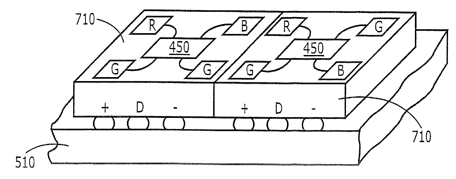
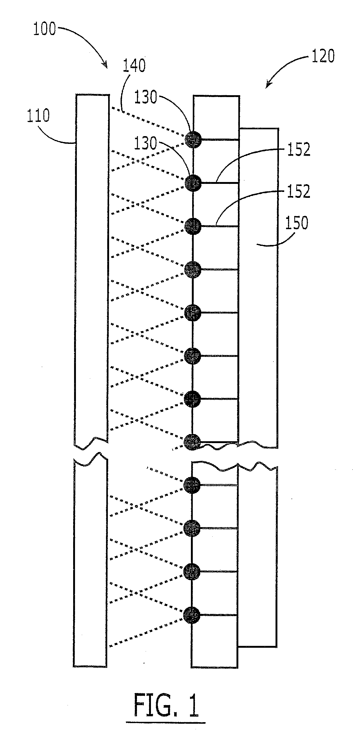
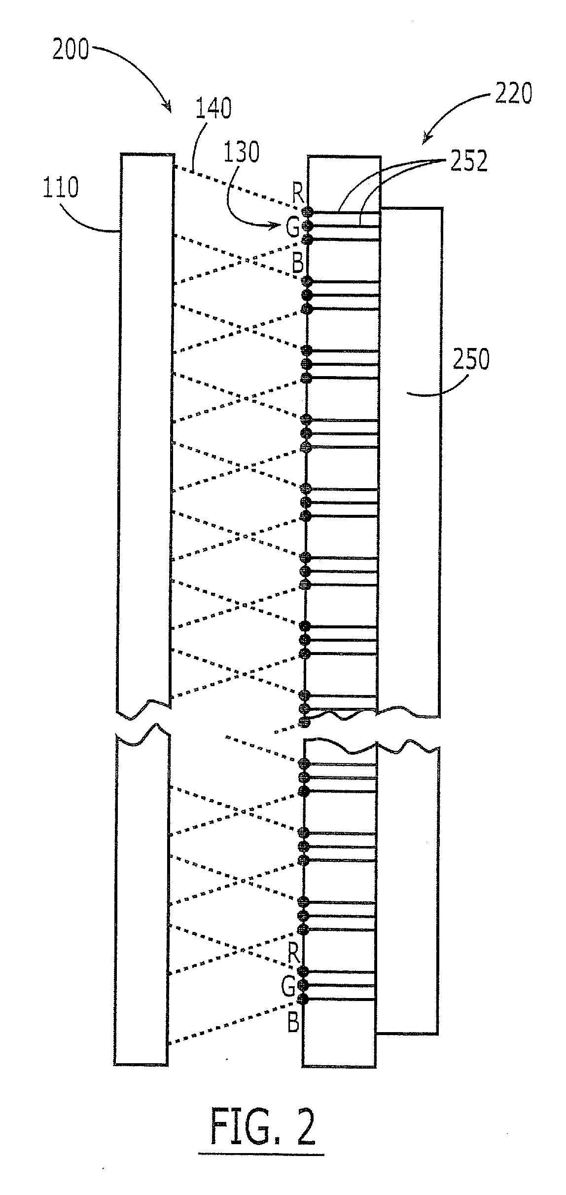
The invention provides edge and direct backlighting systems for color display screens that use LED devices of different colors to provide uniform backlighting and a desired color point. The LED device controller can independently control the operating parameters of subsets, clusters, or individual LED devices to compensate for electrical / optical parameter differences among the LED devices. The invention also provides packaging techniques for mounting LED devices and LED device controllers on a common substrate or a reflector. The technical effects of the invention include improved backlighting control and uniformity, as well as improved color accuracy and consistency.

Problems solved by technology

Unfortunately, an array of fluorescent cold cathode tubes may increase the thickness of the LCD display and / or increase the power consumption thereof.
It also may be difficult to uniformly illuminate the planar array of LCD devices with the array of fluorescent cold cathode tubes.
Unfortunately, this binning may produce additional manufacturing complexity and / or may lead to at least some of the LED devices being rejected as being unsuitable.
Binning and / or rejection of some LED devices also may increase the resultant cost of LED backlighting systems.

Method used


Image

  • Independent control of light emitting diodes for backlighting of color displays
  • Independent control of light emitting diodes for backlighting of color displays
  • Independent control of light emitting diodes for backlighting of color displays

Examples


Embodiment Construction

[0018] The present invention now will be described more fully hereinafter with reference to the accompanying drawings, in which embodiments of the invention are shown. However, this invention should not be construed as limited to the embodiments set forth herein. Rather, these embodiments are provided so that this disclosure will be thorough and complete, and will fully convey the scope of the invention to those skilled in the art. In the drawings, the thickness of layers and regions are exaggerated for clarity. Like numbers refer to like elements throughout. As used herein the term “and / or” includes any and all combinations of one or more of the associated listed items and may be abbreviated as “ / ”.

[0019] The terminology used herein is for the purpose of describing particular embodiments only and is not intended to be limiting of the invention. As used herein, the singular forms “a”, “an” and “the” are intended to include the plural forms as well, unless the context clearly indica...


PUM

PropertyMeasurementUnit
colorsaaaaaaaaaa
electrical/optical parameteraaaaaaaaaa
electrical/opticalaaaaaaaaaa

Abstract

Backlighting systems for color display screens include clusters of LED devices of different colors that are configured to radiate the different colors in a light path that impinges on the color display screen, to provide backlighting on the color display screen. LED device controllers are provided, a respective one of which is configured to control operating parameters of a subset of the clusters of LED devices, a single cluster of LED devices and / or individual LED devices in the individual clusters. The LED device controllers may use a common data line.

Description

CROSS-REFERENCE TO RELATED APPLICATION [0001] This application is a divisional of U.S. application Ser. No. 11 / 185,397, filed Jul. 20, 2005, entitled Independent Control Of Light Emitting Diodes For Backlighting Of Color Displays, assigned to the assignee of the present application, the disclosure of which is hereby incorporated herein by reference in its entirety as if set forth fully herein.FIELD OF THE INVENTION [0002] This invention relates to displays such as Liquid Crystal Displays (LCDs), and more particularly, to backlighting of displays such as LCDs. BACKGROUND OF THE INVENTION [0003] Display screens are widely used for computer monitors, televisions and many other consumer and commercial display applications. Some flat panel display screens include an array of optical shutters and a backlight system that impinges light on the display screen. [0004] For example, LCD devices are widely used in flat panel displays for monitors, televisions and other consumer and commercial di...

Claims


Application Information

Patent Timeline
Patent Type & Authority Applications(United States)
IPC IPC(8): G02F1/13357H01J7/44H05B33/22H01L33/48H01L33/60H01L33/62
CPCG02F1/133603G09G2320/0233G09G3/3426G09G3/32
Inventor NEGLEY, GERALD H.
Owner CREE INC
Learn More