Light emitting device single-cluster lamp control system

a technology of light emitting devices and control systems, which is applied in the direction of instruments, light sources, computing, etc., can solve the problems of difficult replacement of lamps, unalterable lighting effects, and a lot of troubl

Inactive Publication Date: 2006-09-28
OWNWAY TECH
View PDF5 Cites 13 Cited by
  • Summary
  • Abstract
  • Description
  • Claims
  • Application Information

AI Technical Summary

Benefits of technology

[0010] These signal distributors respectively decode video data outputted by the central controller based on address data set by their own address setting units, and respectively transmit the decoded video data via their own interface buffer units to the connected light emitting device single-cluster lamp groups. The present invention makes use of a central controller to separately transmit stored image pattern data to various light emitting device single-cluster lamp groups to display an image pattern or a dynamically varied image pattern corresponding to the video data. Each of the light emitting device single-cluster lamp groups is installed

Problems solved by technology

Because neon lamps are designed to be fixed, their replacement will be difficult after they are installed at a building.
Therefore, the lighting effect is unalterable.
If one wants to make replacement, he needs to disassemble the whole neon lamp, hence taking a lot of trouble.
Besides, the power consumption for light emission of a neon lamp is large.
This is the prim

Method used


Image

  • Light emitting device single-cluster lamp control system
  • Light emitting device single-cluster lamp control system
  • Light emitting device single-cluster lamp control system

Examples


Embodiment Construction

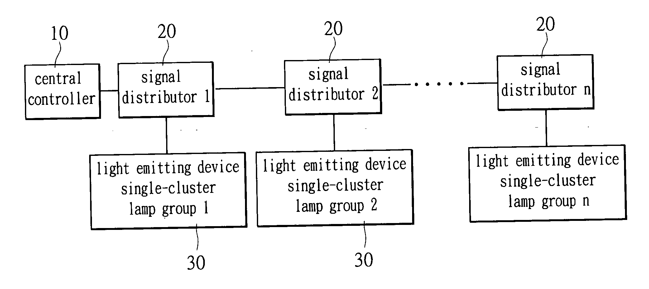
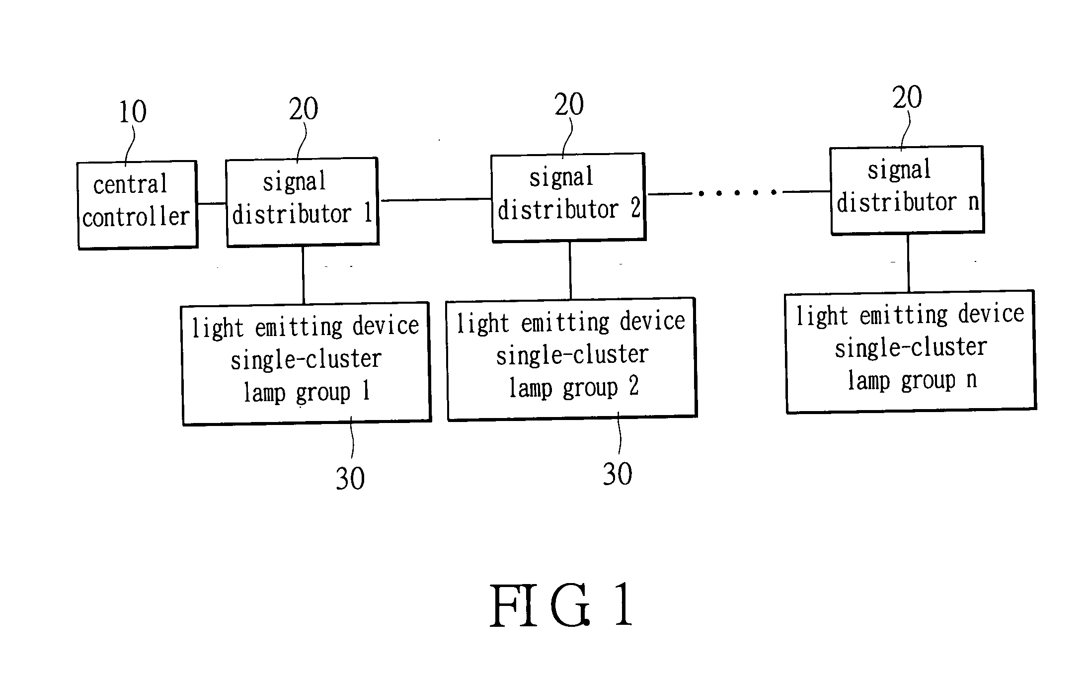
[0017] As shown in FIG. 1, a central controller 10 controls one or a plurality of signal distributors 20 to transmit at least a video data outputted by the central controller 10 to various light emitting device single-cluster lamp groups 30 (i.e., display units) Each of the light emitting device single-cluster lamp groups 30 is composed of several light emitting device single-cluster lamps. The present invention is characterized in a multi-object function, i.e., a central controller 10 can control several display units to display a pattern through software editing.

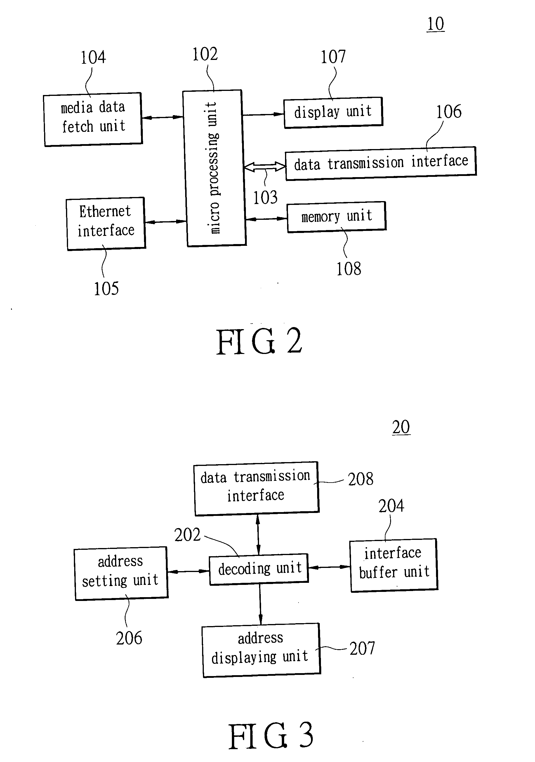
[0018] Reference is made to FIG. 2 as well as FIG. 1. The central controller 10 comprises a micro processing unit 102, which is connected with a memory unit 108, a media data fetch unit 104, a display unit 107, and an Ethernet interface 105. The micro processing unit 102 is also connected to a data transmission interface 106 via a serial bus 103.

[0019] The micro processing unit 102 controls the media data fetch unit 104 ...


PUM


Abstract

A light emitting device single-cluster lamp control system makes use of a central controller connected with several mutually cascading signal distributors to process already-edited video or multimedia. The central controller then outputs different video data based on the processed video or multimedia, and separately sends the video data via these signal distributors to various light emitting device single-cluster lamp groups to display an image pattern corresponding to the video data. Each light emitting device single-cluster lamp group is installed at a light emitting body (e.g., a building lighting, a landscape lighting, or a billboard) composed of several light emitting device single-cluster lamps.

Description

BACKGROUND OF THE INVENTION [0001] 1. Field of the Invention [0002] The present invention relates to a light emitting device single-cluster lamp control system, which separately sends different video data to various light emitting device single-cluster lamp groups to display an image corresponding to the video data. [0003] 2. Description of Related Art [0004] The discovery of electricity and the invention of lamps make lighting no longer limited by natural light sources. Along with the development of the electronics industry, lightings based on electricity become more and more diversified. In addition to night lightings, decorative lightings with visual effects like neon lamps, lasers, light emitting diodes (LEDs), and so on have also been developed. The utmost feature of these decorative lighting is that they can form various patterns. Moreover, Neon lamps can be provided around a large building to show the profile of this building with light from these lamps, hence achieving a pre...

Claims


Application Information

Patent Timeline
IPC IPC(8): G09G3/14
CPCG06F3/1446G09G2370/04H05B37/029H05B47/155
Inventor YU, TE-CHENGSUN, SHANG-CHELAI, CHIH-WEICHIU, HUANG-TALIN, WAN-CHIHLIAO, HAO-FANHSU, MING-CHU
Owner OWNWAY TECH
Why Eureka
Try Eureka