
Interferometer-based chromatic dispersion monitor

Inactive Publication Date: 2008-01-24
USA AS REPRESENTED BY THE SEC OF THE NAVY THE
View PDF8 Cites 10 Cited by
  • Summary
  • Abstract
  • Description
  • Claims
  • Application Information

AI Technical Summary

Problems solved by technology

In long fiber spans, this spreading can lead to bit errors.
However, in some systems practicing this method, extra tones added to the transmission result in spurious signals at the receiver.
Using a two photon absorber requires short pulses, limiting it s use to high data rate RZ systems.

Method used


Image

  • Interferometer-based chromatic dispersion monitor
  • Interferometer-based chromatic dispersion monitor
  • Interferometer-based chromatic dispersion monitor

Examples


Embodiment Construction

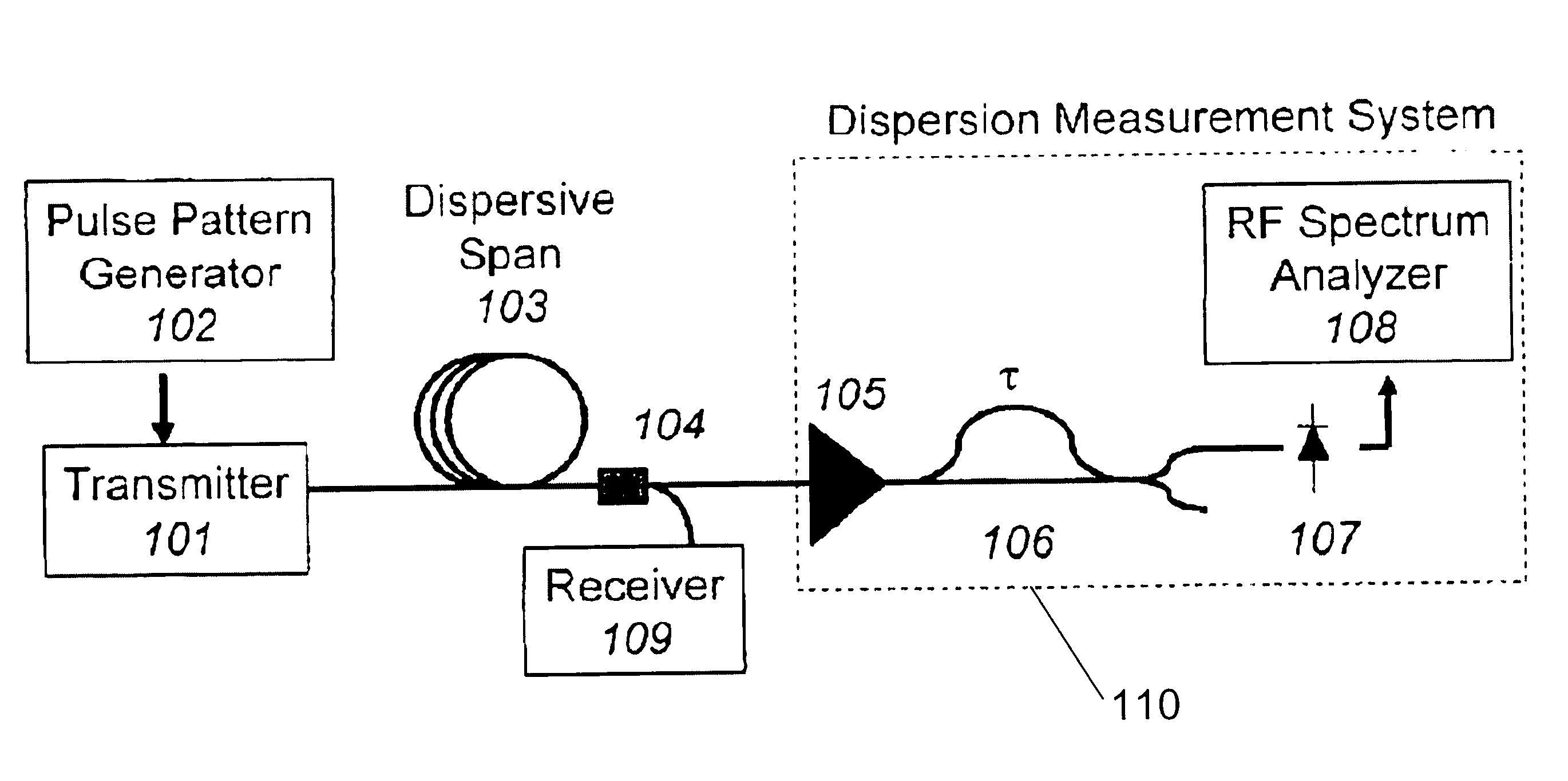
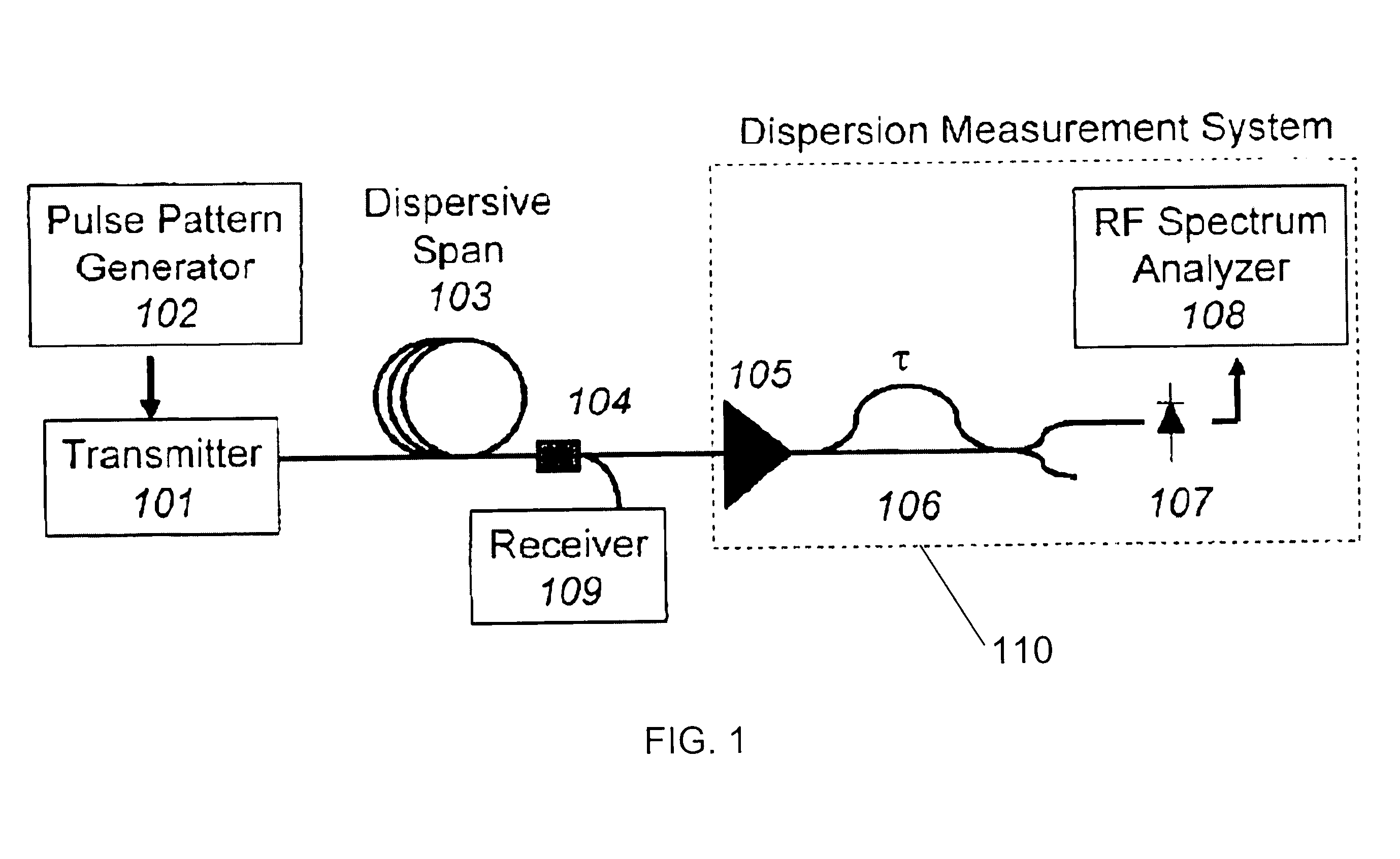
[0016]An embodiment of the invention is based on the evolution of the RF spectrum of the transmitted data as it propagates along a dispersive fiber. For an intensity modulated double sideband (IM-DSB) signal transmitted along the fiber, dispersion converts some of the intensity modulated signal into phase modulation. Therefore, by measuring the phase modulation present at a specific spectral component, the dispersion of the link is determined. Such measurement is, for example, accomplished using an interferometer, such as a path imbalanced Mach-Zehnder interferometer (“MZI”).

[0017]The signal produced by the MZI is, for example, determined by considering the evolution of a spectral component at frequency Ω during propagation along the fiber. As the carrier (ω0) and sidebands (ω0±Ω) propagate along the fiber, they acquire phase shifts of φ0 and φ±, respectively. This produces an electric field with both intensity and phase modulation components at Ω. If the signal is then sent through...


PUM


Abstract

An apparatus includes a first portion operable to convert an optical phase modulation component of a signal being transmitted through a fiber to a RF intensity modulation, the RF intensity modulation comprising a magnitude; and a second portion operable to determine a dispersion of the fiber based on the magnitude of the RF intensity modulation. Optionally, the first portion includes a path-imbalanced interferometer and an optical intensity detector communicating therewith. Optionally, the apparatus further includes a dispersion compensator communicating with the second portion. Optionally, the second portion includes a filter detector or a coherent detector. Optionally, the filter detector includes a bandpass filter and a Schottky diode, and the coherent detector includes a heterodyne detector or a homodyne detector.

Description

CROSS-REFERENCE TO RELATED APPLICATION[0001]The application claims priority of U.S. Provisonal Patent Application Ser. No. 60 / 803,526, entitled “INTERFEROMETER BASED CHROMATIC DISPERSION MONITOR,” to Campillo.TECHNICAL FIELD[0002]The present invention relates generally to a monitor of chromatic dispersion in optical fibers, and more particularly to a chromatic dispersion monitor for use in a system having a time varying dispersion.BACKGROUND ART[0003]Chromatic dispersion in optical fibers causes a spreading of transmitted data pules. In long fiber spans, this spreading can lead to bit errors. To prevent these errors, dispersion compensating sections are added to the span. For systems with time varying dispersion, real-time monitoring and compensation is required.[0004]Several methods have been developed for real time chromatic dispersion monitoring. One method for real-time chromatic dispersion monitoring involves monitoring tones added to the transmitted signal. Examples of this me...

Claims


Application Information

Patent Timeline
IPC IPC(8): H04B10/12H04B10/04
CPCH04B10/07951
Inventor CAMPILLO, ANTHONY L.
Owner USA AS REPRESENTED BY THE SEC OF THE NAVY THE
Learn More