Measuring apparatus and measuring method

A measuring device and one-party technology, applied in measuring devices, measuring heat, measuring optics, etc., can solve problems such as low beat signal frequency

Active Publication Date: 2016-10-12
OKI ELECTRIC IND CO LTD
View PDF7 Cites 9 Cited by
  • Summary
  • Abstract
  • Description
  • Claims
  • Application Information

AI Technical Summary

Problems solved by technology

[0010] Here, since the probe light is subjected to a frequency shift of about the Brillouin frequency by the optical frequency shifter 143, the frequency of the beat signal generated by the heterodyne detection becomes lower.

Method used


Image

  • Measuring apparatus and measuring method
  • Measuring apparatus and measuring method
  • Measuring apparatus and measuring method

Examples


no. 1 approach

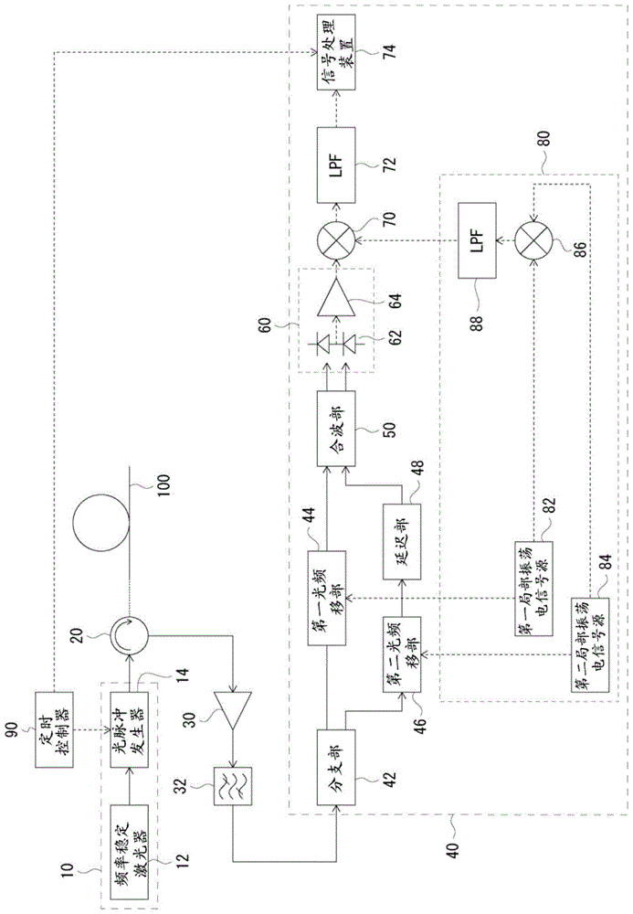
[0037] refer to figure 1 , the optical fiber distortion measurement device (hereinafter also referred to as the first optical fiber distortion measurement device.) of the first embodiment will be described. figure 1 is a schematic block diagram of the first optical fiber distortion measuring device.

[0038] The first optical fiber distortion measurement device is configured to include a light source unit 10 , a circulator 20 , an optical amplifier 30 , an optical bandpass filter 32 , a self-delay heterodyne interferometer 40 , and a timing controller 90 .

[0039] The light source unit 10 generates probe light. The light source unit 10 is configured to include a light source 12 that generates continuous light, and an optical pulse generator 14 that generates optical pulses from the continuous light.

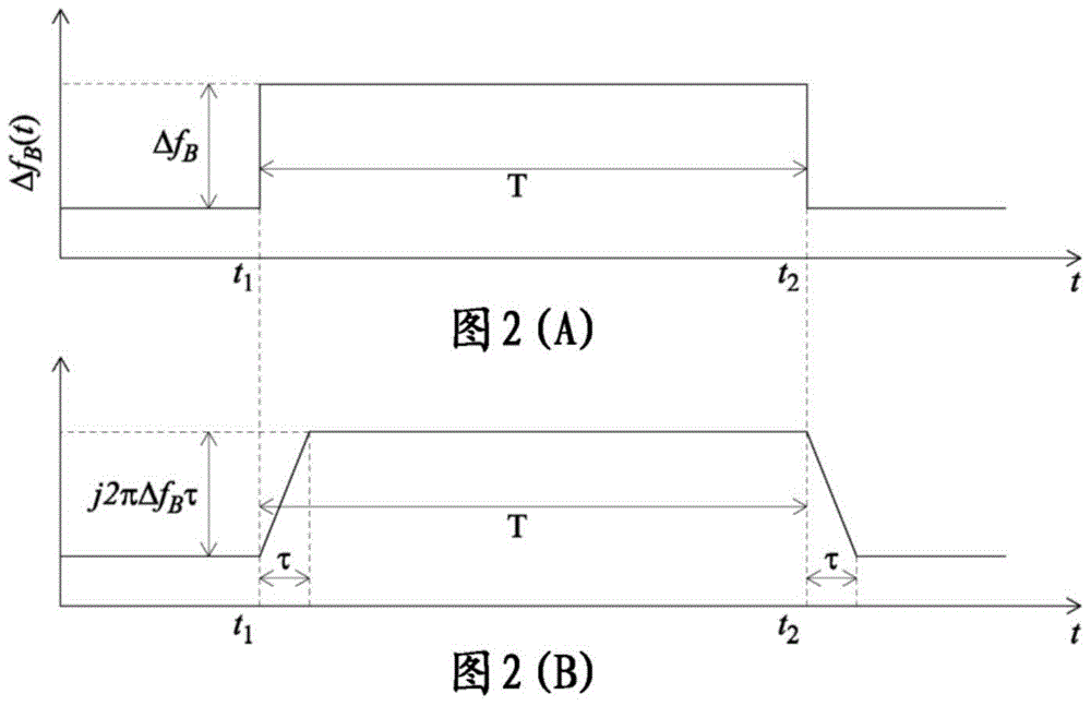
[0040] Here, the first optical fiber distortion measurement device measures the phase difference corresponding to the frequency change. Therefore, the frequency fluctuation...

no. 2 approach

[0068] refer to Figure 4 , an optical fiber distortion measurement device (hereinafter, also referred to as a second optical fiber distortion measurement device) according to a second embodiment will be described. Figure 4 is a schematic block diagram of the second optical fiber distortion measuring device.

[0069] The difference between the second optical fiber distortion measurement device and the first optical fiber distortion measurement device is that there is only one optical frequency shifter 43 of the self-delay heterodyne interferometer 41 . Here, although an example is shown in which the optical frequency shift unit 43 is provided on the second optical path, it may also be provided on the first optical path.

[0070] Since there is one optical frequency shifting unit, there is also one local oscillation electrical signal source 83 included in the electrical signal generating unit 81 . In addition, the electrical signal from the local oscillation electrical signa...

no. 3 Embodiment approach

[0073] refer to Figure 5 , an optical fiber distortion measurement device (hereinafter also referred to as a third optical fiber distortion measurement device) of a third embodiment will be described. Figure 5 is a schematic block diagram of a third optical fiber distortion measuring device.

[0074] The third optical fiber distortion measurement device differs from the first optical fiber distortion measurement device in that it does not include an optical frequency shift unit.

[0075] In this case, the coherent detection unit 60 performs homodyne detection to generate a beat signal. Since the beat signal corresponds to the phase difference signal as usual, an electric signal generation unit, a frequency mixing unit, and an LPF are not required.

[0076] The third optical fiber distortion measurement device corresponds to setting f in the above formulas (1) to (5) 1 =f 2 =0, Δf=0. Since the 3rd optical fiber distortion measuring device does not have an optical frequen...


PUM


Abstract

The invention relates to a measuring apparatus and a measuring method. The measuring apparatus includes a light source unit configured to generate probe light, a bifurcating unit configured to cause Brillouin backscattered light occurring from the probe light to bifurcate into first light, which propagates through a first optical path, and second light, which propagates through a second optical path, a delay unit configured to delay one of the first light and the second light, an optical multiplexer configured to multiplex the first light and the second light to generate multiplexed light, and a coherent detector configured to perform homodyne detection of the multiplexed light and to output a difference frequency obtained as a result of the detection as a phase-difference signal. According to provided method, when Brillouin backscattered light is used to measure distortion of optical fibers, the measured frequency change of light is taken as the phase-difference of beat signal provided by coherent detection, and thus two-dimensional information of time and phase can be obtained.

Description

technical field [0001] The present invention relates to a measuring device and a measuring method using Brillouin scattered light. Background technique [0002] With the development of optical fiber communication, distributed optical fiber sensing with optical fiber itself as the sensing medium has been widely studied. In distributed optical fiber sensing, it is represented by Optical Time Domain Reflectometry (OTDR: Optical Time Domain Reflectometry). Backscattered light. There are Rayleigh scattering, Brillouin scattering, and Raman scattering as backscattering in an optical fiber. Among them, the measurement of natural Brillouin scattering is called BOTDR (Brillouin OTDR: Brillouin Optical Time Domain Reflectometer) (see, for example, Non-Patent Document 1). [0003] Brillouin scattering is observed at a place where the center frequency of the optical pulse incident on the fiber is shifted by GHz on the Stokes side and the anti-Stokes side, and this spectrum is called ...

Claims


Application Information

Patent Timeline
Patent Type & Authority Applications(China)
IPC IPC(8): G01D5/353
CPCG01D5/35364G01J3/4412G01J9/04G01K11/32G01K11/322
Inventor 小泉健吾
Owner OKI ELECTRIC IND CO LTD
Why Eureka
Try Eureka