
Air conditioner and method of controlling air conditioner

Inactive Publication Date: 2008-01-31
DENSO CORP
View PDF1 Cites 22 Cited by
  • Summary
  • Abstract
  • Description
  • Claims
  • Application Information

AI Technical Summary

Benefits of technology

[0007]Another object of the present invention is to provide an air conditioner and a method of controlling the air conditioner that has a sufficiently large heating capacity without increasing noise and increasing fuel consumption.
[0009]Due to the above constitution, in the case where a temperature of the medium is low, the refrigerating cycle can be easily stopped. Therefore, it is possible to suppress a decrease in the temperature of the medium. As a result, heating capacity can be enhanced. In this connection, a reduction in the compression ratio of the refrigerant includes a stoppage of compressing the refrigerant, that is, a reduction in the compression ratio of the refrigerant includes a stoppage of the compressor.
[0011]It is preferable that the compressor control unit sets the threshold temperature at a higher value when the medium temperature becomes lower than the first predetermined temperature. Due to the above constitution, the lower the medium temperature is, the more easily the refrigerating cycle can be stopped. Accordingly, a reduction in the heating capacity caused by a decrease in the medium temperature can be effectively suppressed.

Problems solved by technology

Therefore, an air conditioner for a vehicle, which warms up blown air by a heater core utilizing an engine coolant, cannot sufficiently warm up an operator cab in some cases, especially when idling in winter, since the temperature of the engine coolant is too low.
Therefore, it is difficult to decrease the temperature of the evaporator of the air conditioner until the evaporator is frosted over.
Therefore, in the air conditioner mounted in the construction vehicle, blown air which has been cooled by the evaporator, flows into a heater core for a prolonged period of time.
However, as described above, in the idling control device described in Patent Document 1, controlling is conducted so that the engine speed can be raised, and as a result engine noise is increased and fuel consumption is increased.

Method used


Image

  • Air conditioner and method of controlling air conditioner
  • Air conditioner and method of controlling air conditioner
  • Air conditioner and method of controlling air conditioner

Examples


Embodiment Construction

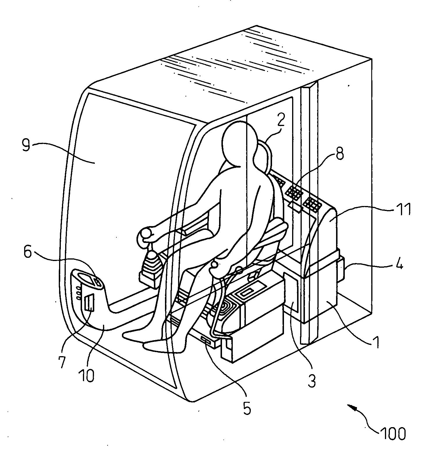
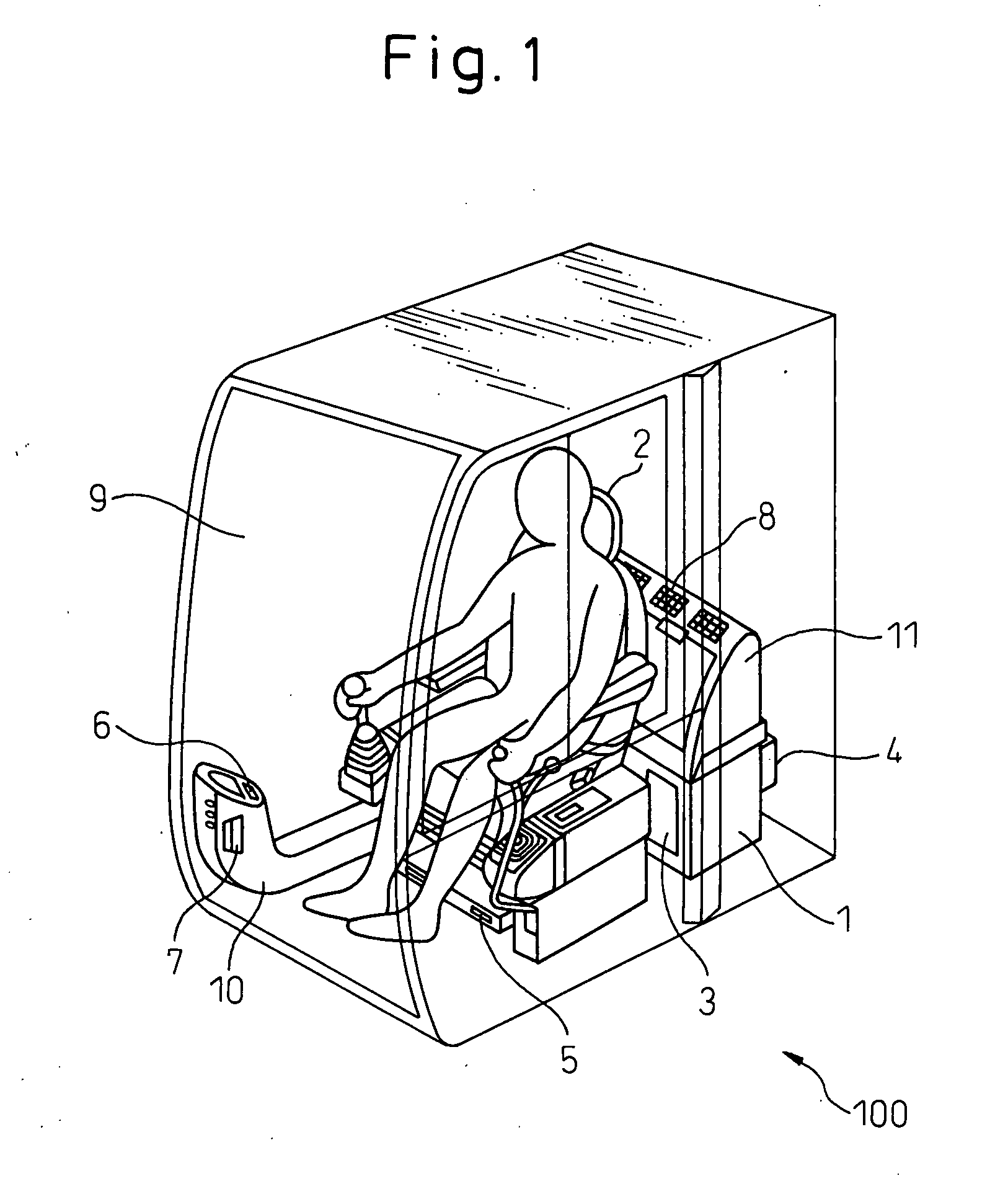
[0025]Referring to the drawings, an air conditioner for a vehicle of the present invention will be explained below. However, it should be noted that the present invention is not limited by the following explanations.

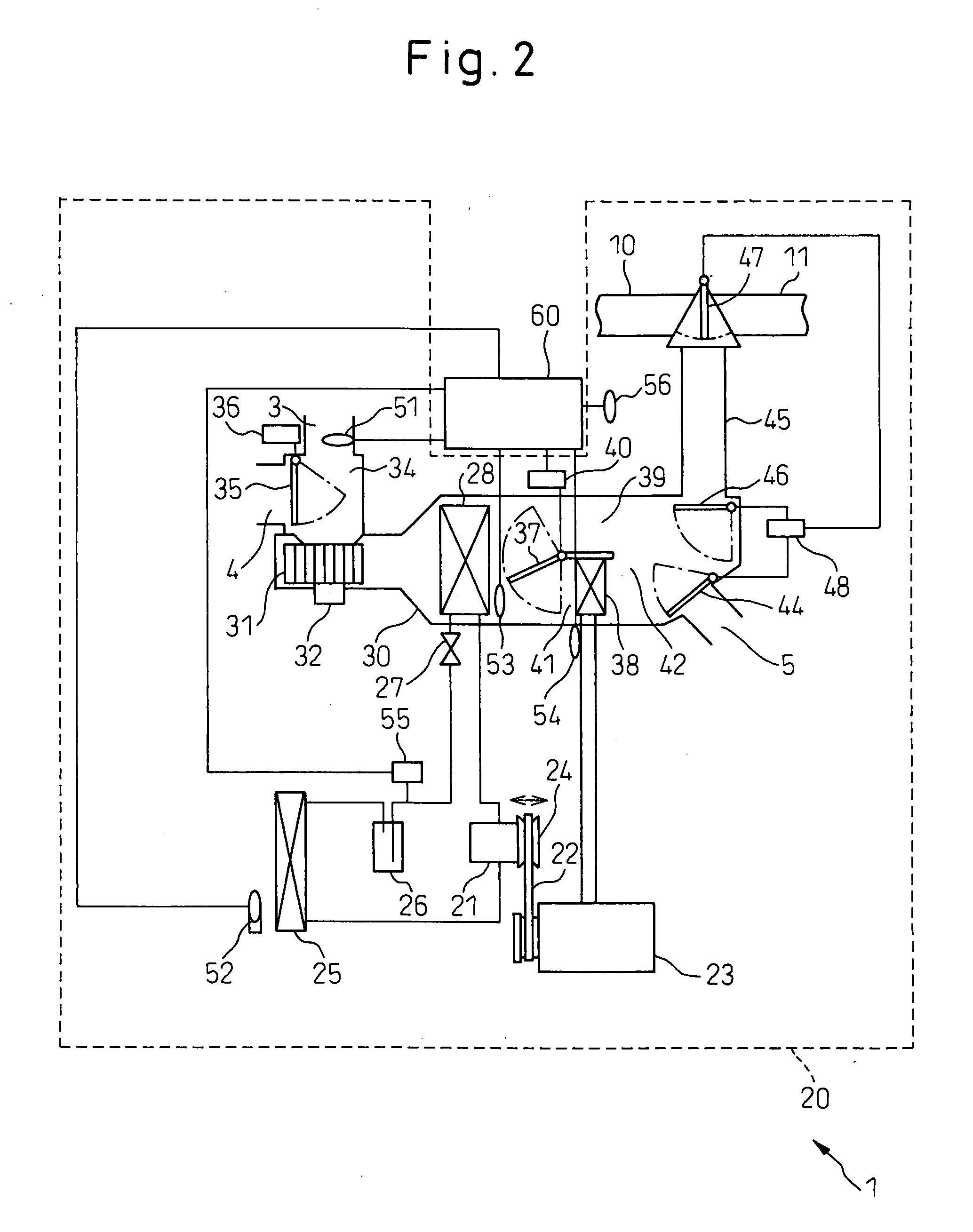
[0026]The air conditioner for a vehicle according to the present invention, in order to extend a period of time in which the compressor is stopped, sets an evaporator temperature, at which the compressor of the refrigerating cycle is stopped, at a value higher than a threshold temperature for preventing the evaporator from frosting over, by referring to engine coolant temperature supplied to the heater core. However, a setting range of the evaporator temperature is determined so that a windshield or door of an operator cab can be defogged in the setting range of the evaporator temperature. When the compressor is controlled as described above, in the air conditioner for a vehicle, the temperature of air flowing into the heater core is prevented from decreasing so that hea...


PUM


Abstract

An air conditioner comprises: a refrigerating cycle including a compressor and an evaporator; a heater core for heating the air that has passed through the evaporator; a first sensor for acquiring information related to a temperature of the evaporator; a second sensor for acquiring information related to a temperature of a medium to supply heat to the heater core; and a compressor control unit for controlling the compressor. When the temperature of the evaporator is not higher than a predetermined threshold temperature, the compressor control unit reduces a ratio of compression of the refrigerant by the compressor. When the temperature of the medium is not more than a first predetermined value, the compressor control unit sets the threshold temperature at a value higher than a frost limit temperature of the evaporator.

Description

[0001]The applicant claims the right of priority based on Japanese Patent Application JP 2006-208674, filed on Jul. 31, 2006, and the entire content of JP-2006-208674 is hereby incorporated by reference.FIELD OF THE INVENTION[0002]The present invention relates to an air conditioner and a method of controlling the air conditioner. More particularly, the present invention relates to an air conditioner and a method of controlling the air conditioner by which an operator cab is heated and a windshield of the operator cab is defogged at the same time.BACKGROUND OF THE INVENTION[0003]Recently, strict emission control laws have been enacted. Accordingly, there is a tendency for heat produced by an engine mounted on a construction vehicle such as a hydraulic excavator is reduced. Therefore, an air conditioner for a vehicle, which warms up blown air by a heater core utilizing an engine coolant, cannot sufficiently warm up an operator cab in some cases, especially when idling in winter, since...

Claims


Application Information

Patent Timeline
IPC IPC(8): F24F11/02B60H1/32
CPCB60H1/321B60H2001/3261B60H2001/3266F25B2600/02F24F11/0009F24F11/0012F24F2011/0045B60H2001/327F24F11/30F24F2110/10F24F2140/20F24F11/77F24F11/86F24F11/63F24F11/41
Inventor FUKUTA, KAZUHIRO
Owner DENSO CORP
Learn More