Tube capper/decapper

a technology of capping and decapping tubes, which is applied in the direction of closure stoppers, open-closed containers, packaging goods, etc., can solve the problems of bulky systems, tediousness, slowness,

Active Publication Date: 2008-01-31
THE AUTOMATION PARTNERSHIP CAMBRIDGE
View PDF13 Cites 34 Cited by
  • Summary
  • Abstract
  • Description
  • Claims
  • Application Information

AI Technical Summary

Benefits of technology

[0010]A particular advantage of the clutch system of the capper/de-capper and method according to the invention is t

Problems solved by technology

This is not only tedious (in the case of manual capping/de-capping), but also slow as it is usual for plural tubes to require processing in the same way at the same time.
It is known to provide a linear array of cappers/de-cappers to allow capping/de-capping of a row of tubes, but such systems have

Method used


Image

  • Tube capper/decapper
  • Tube capper/decapper
  • Tube capper/decapper

Examples


Embodiment Construction

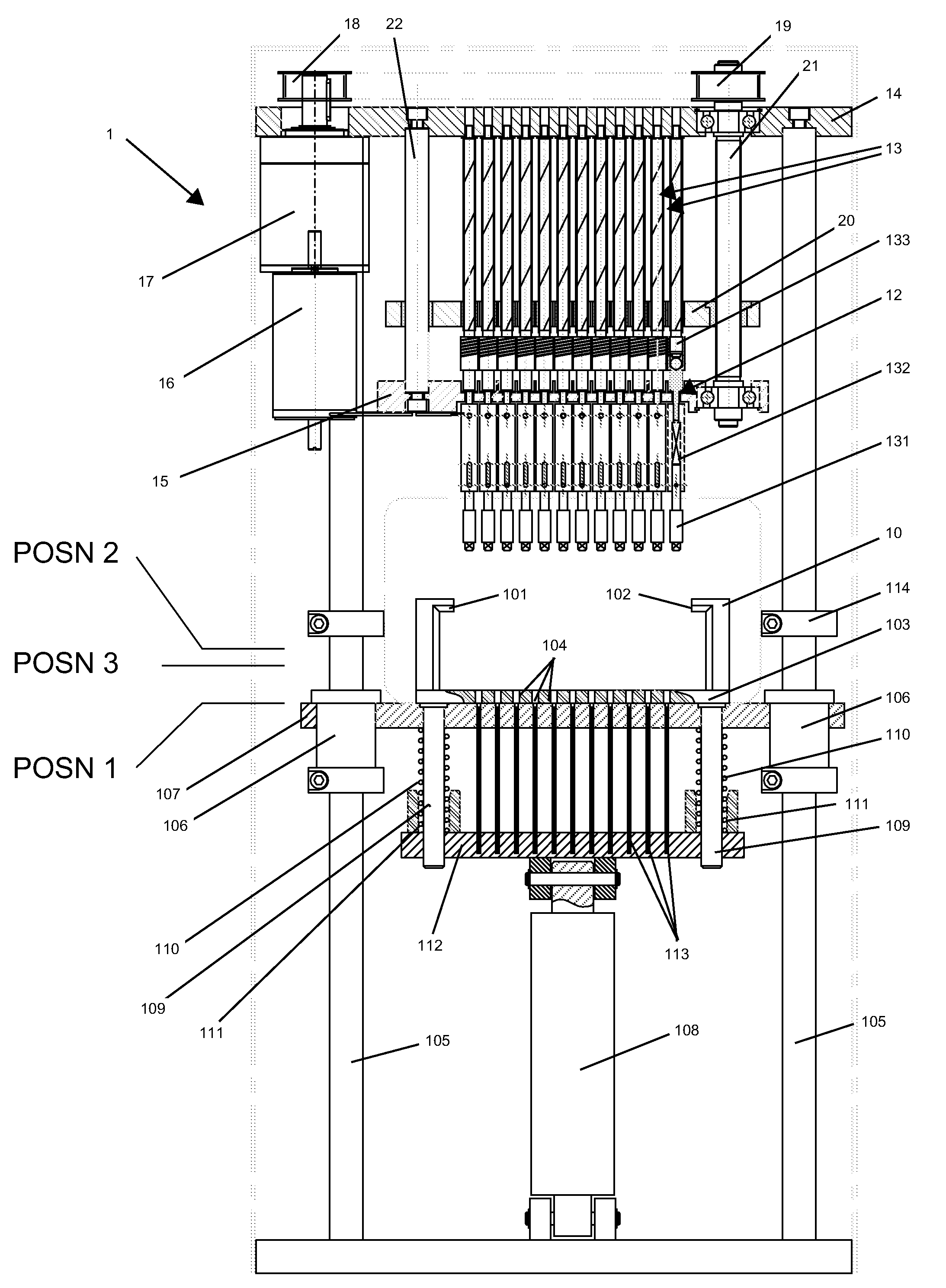
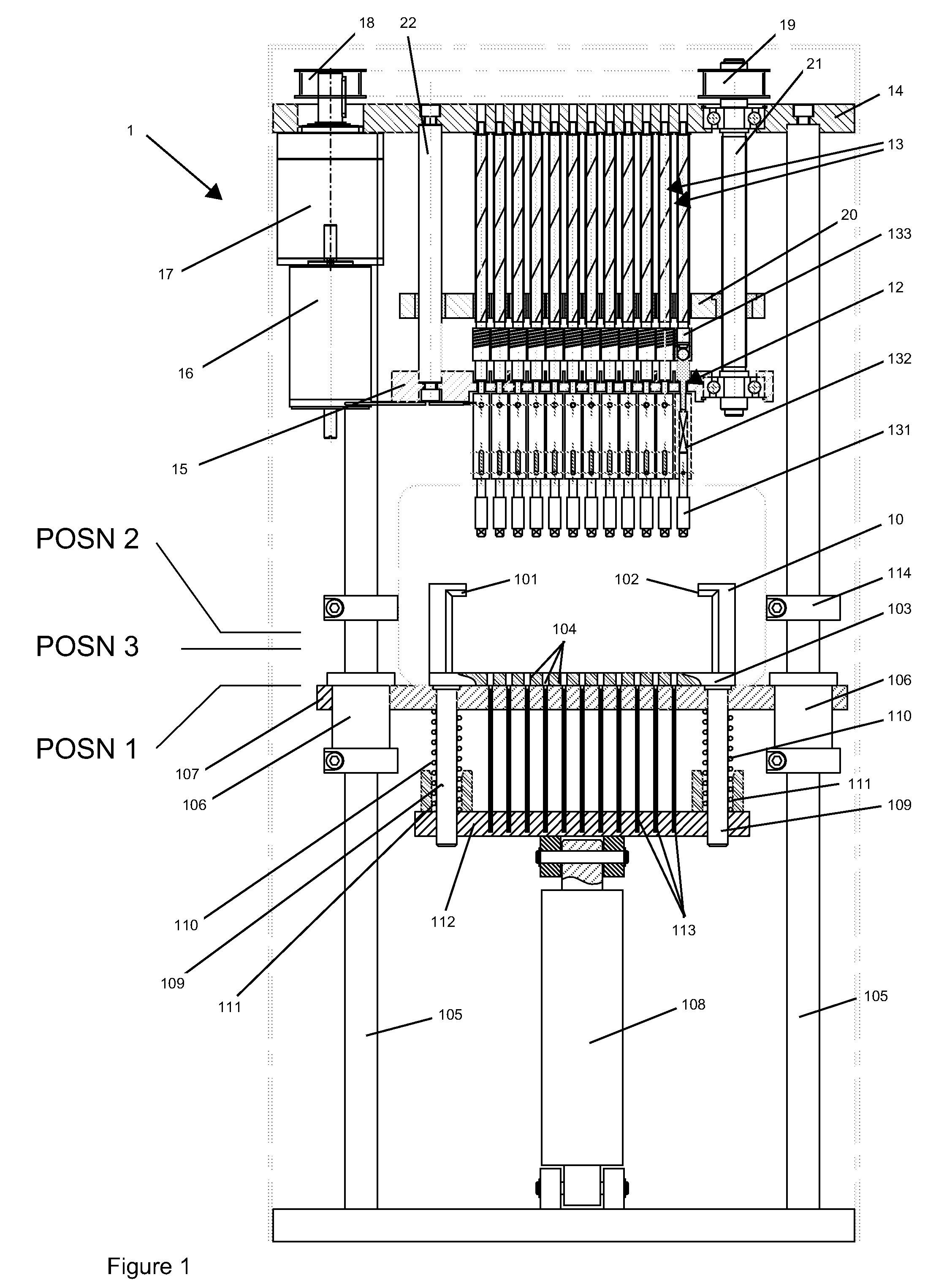
[0028]The capper / de-capper system 1 shown in the drawings comprises a standalone system for capping and uncapping screw-cap tubes and is designed as a bench-top system for use in either a laboratory or within a micro-biological control cabinet.

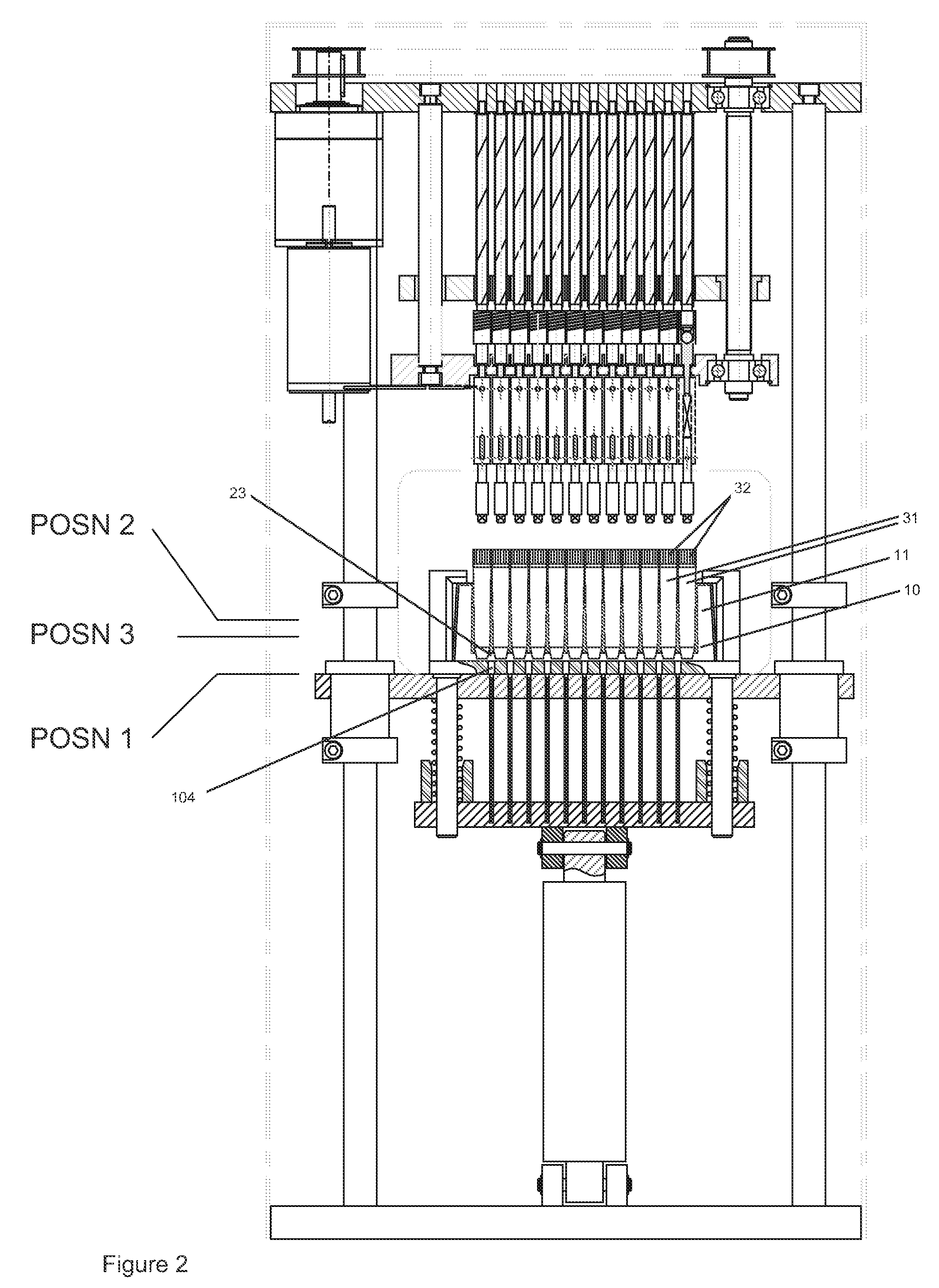
[0029]The system 1 includes a rack support 10 which is dimensioned, in this example, specifically to receive a standard 96-well SBS format rack 11 (see FIG. 2) in a defined and fixed horizontal position relative to a head unit 12.

[0030]The head unit 12 includes 96 capping / de-capping spindles 13 arranged in an 8 by 12 two-dimensional array.

[0031]FIG. 18 is series of views of one of the spindles 13 shown in more detail. It can be seen that the spindle 13 includes a capper / de-capper spigot 131 which is spring-loaded by a compression spring 132 and rotatably driven through a clutch 133. Each of the clutches 133 may comprise a spring wrap clutch as shown in FIG. 18, but various alternatives are possible and, for example, the clutch may comprise a p...


PUM

PropertyMeasurementUnit
Torqueaaaaaaaaaa

Abstract

A capper/de-capper system 1 has a rack support 10 for supporting a rack 11 containing a plurality of capped tubes 31 in a given position. A head unit 12 supports a two-dimensional array of capping/de-capping spindles 13, each of which includes a clutch 133 and a capping/de-capping spigot 131 or socket, the spindles being aligned with the tube positions defined in the rack. A drive mechanism 108 moves the tubes and the head unit relatively towards and away from one another in use, when a rack containing capped tubes is disposed in the rack support, causing engagement and disengagement of the capping/de-capping spigots or sockets with and from the tube caps 32. A spindle drive system 15-22 provides simultaneous rotation of the capping/de-capping spigots or sockets together after engagement with the caps, either to detach caps from the tubes or attach caps to the tubes.

Description

BACKGROUND[0001]The present invention relates to a capper / de-capper device and method for attaching and removing caps from tubes, and, more particularly, a device and method for removing screw-threaded caps from tubes such as microtubes used in laboratories or micro-biological systems.[0002]High value biological samples are often stored and processed using so-called SBS format racks containing a plurality of tubes. Such racks may contain, for example, 96 tubes in an array of 8 by 12 apertures designed to hold the tubes securely. The tubes and their contents may be manoeuvred in a processing system, for example between a cold store and various processing stations and may be required to be filled (partly or fully) or processed simultaneously or individually.[0003]Conventionally, capping / de-capping has either been carried out by hand or else by means of a capping / de-capping unit individually engageable with the tubes either while they are still held in the rack or else after they have ...

Claims


Application Information

Patent Timeline
IPC IPC(8): B67B7/18
CPCB01L3/50825G01N2035/0405G01N35/026
Inventor OWEN, STEPHENOWEN, JUSTINBARGH, ADRIAN NEIL
Owner THE AUTOMATION PARTNERSHIP CAMBRIDGE
Why Eureka
Try Eureka