
Adsorption heat exchanger

a heat exchanger and adsorption technology, applied in the field of adsorption coated heat exchangers, can solve the problems of uneven heat dissipation of adsorbent coating layer, uneven thickness of adsorption coating layer, etc., and achieve the effect of reducing heat dissipation and mass transfer, reducing heat dissipation and heat dissipation, and reducing heat dissipation

Inactive Publication Date: 2008-01-31
HONEYWELL INT INC
View PDF35 Cites 27 Cited by
  • Summary
  • Abstract
  • Description
  • Claims
  • Application Information

AI Technical Summary

Problems solved by technology

Although the described adsorption heat exchanger can reduce power input, the adsorptive material tends to build up at the tube-plate interface during coating application.
The uneven adsorptive coating layer reduces efficiency.
Although the laminate paper can provide a more even layer of adsorptive material, both heat and mass transfer are negatively affected by the thickness of adsorptive material / fiber matrix paper.

Method used


Image

  • Adsorption heat exchanger
  • Adsorption heat exchanger
  • Adsorption heat exchanger

Examples


example 1

[0058]A plot of specific power (kW / kg) as a function of cycle time (sec.) is shown in FIG. 6. As it can be seen, high specific power can be achieved at a much shorter cycle time in comparison with current tube-plate design. Several fin densities (fpi) for the adsorption layer were considered. Wash coating process calls for optimum fpi number. An fpi number of more then 11 may not be suitable for some applications due to poor drainage of extra wash coat after its application onto the fin-plate structure.

example 2

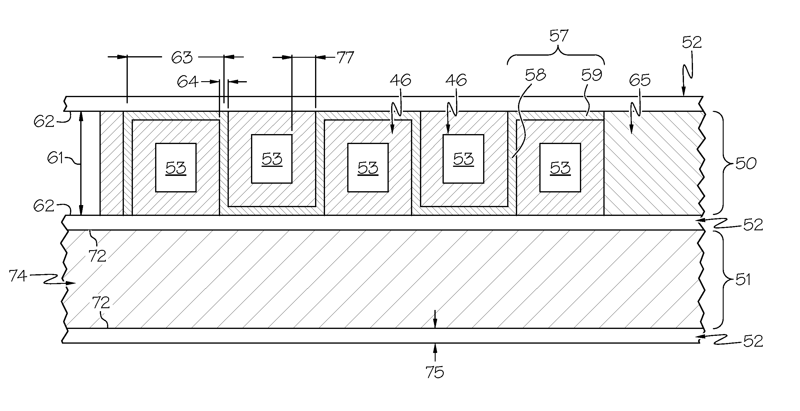
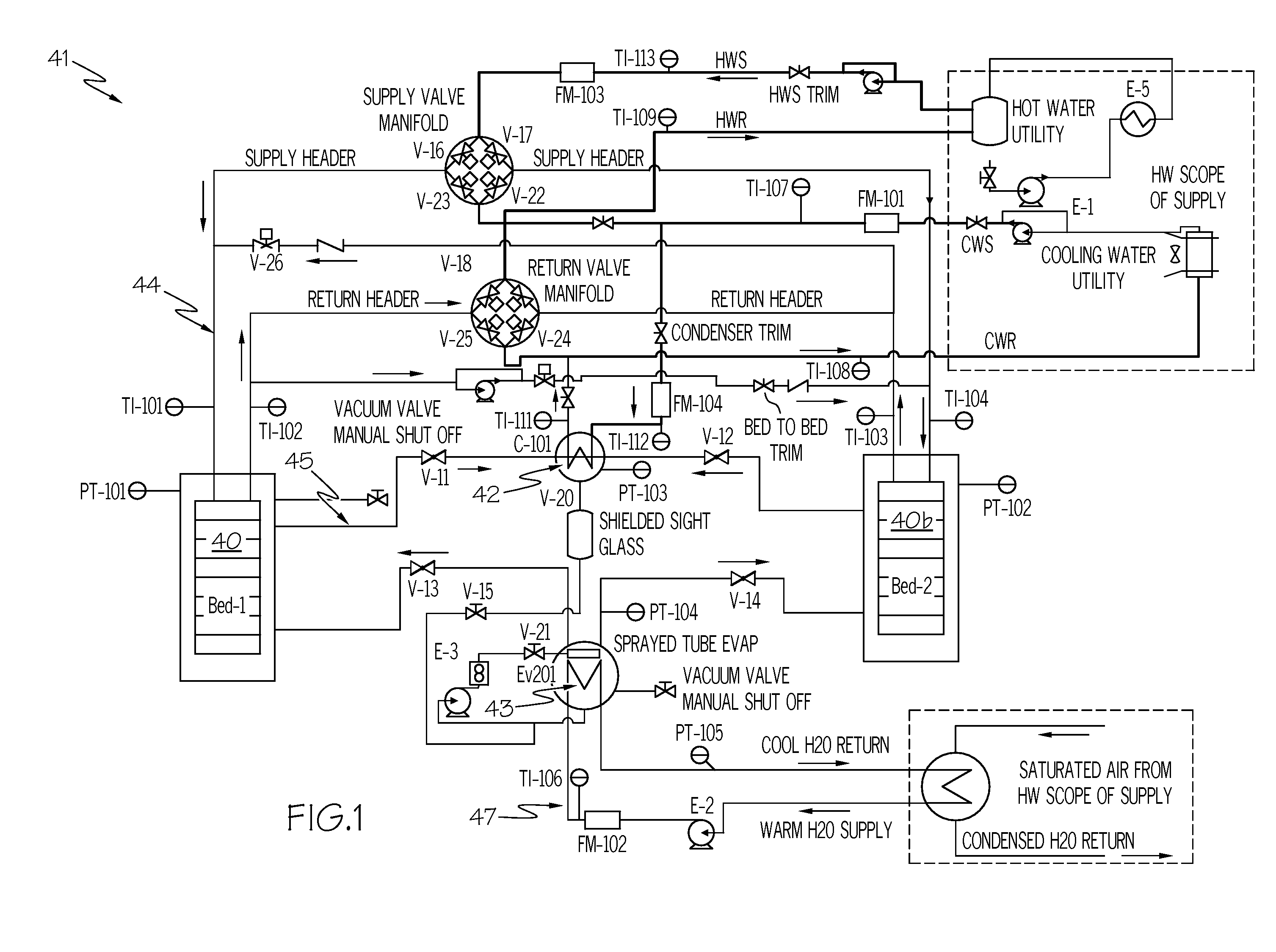
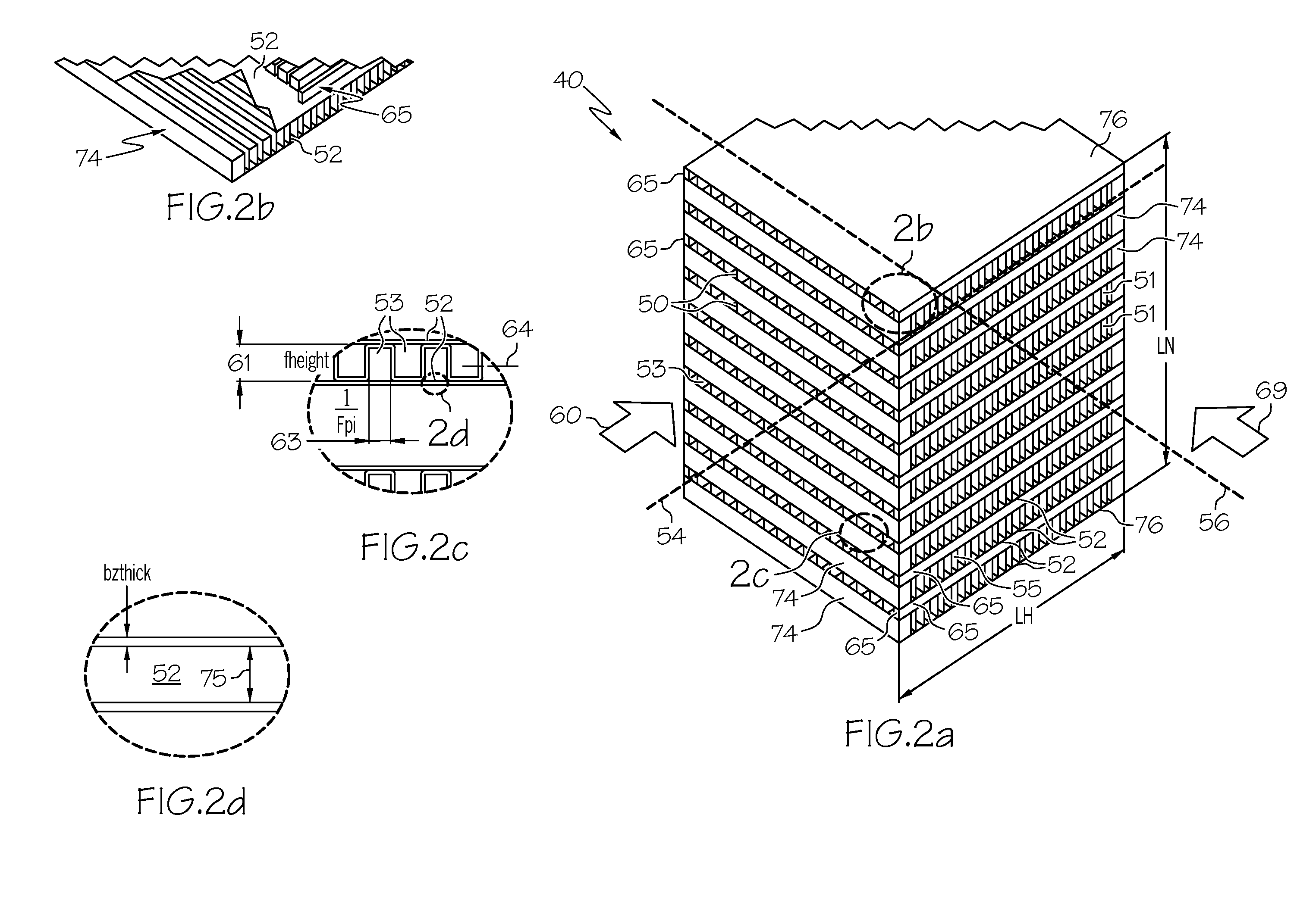
[0059]The design parameters for one embodiment of the present invention are shown FIG. 7. In this example, the components (fins, plates, etc.) comprise aluminum. Dynamic simulation results of h for adsorption side (h=553 / BTU / hr.ft2.R) and fpi=11 were used for the adsorption heat exchanger design. The calculated design parameters for adsorption side (adsorption layer 50) and HT side (Ethylene Glycol / Water, (EGW) (heat transfer layer 51) are shown in FIG. 7. During the sorptive cooling process, adsorption / desorption side of adsorption heat exchanger was under a total pressure of 5-80 torr depending on the mode (i.e. adsorption or desorption). The geometry of an embodiment of the adsorption heat exchanger is shown on FIG. 8. The estimated adsorption heat exchanger core dry weight is 6.7 lb. As can be seen, embodiments of the present invention can increase adsorptive material surface area while reducing adsorption heat exchanger overall dimensions.

example 3

[0060]The sensitivity results on adsorption material coating thickness variations are shown in FIG. 9. The results show that specific power decreases when adsorption material coating thickness increases. Absolute cooling power increases with the increased adsorption material coating thickness. It should be noted here that adsorption side heat transfer coefficient would be slightly changed due to different adsorption material coating thickness, which was not considered in the sensitivity study.


PUM

PropertyMeasurementUnit
Thicknessaaaaaaaaaa
Thicknessaaaaaaaaaa
Thicknessaaaaaaaaaa

Abstract

An adsorption heat exchanger may comprise a stack of alternating adsorption layers and heat transfer layers. Separator plates may separate the adsorption layers from the heat transfer layers. The adsorption layer may include a first corrugated sheet positioned between and brazed to the adsorption zone facing side of two separator sheets. The first corrugated sheet and the exposed portions of the adsorption zone facing side of the separator sheets may be coated with an adsorptive material. The heat transfer layer may include a second corrugated sheet positioned between and brazed to the heat transfer zone facing side of two separator sheets. The second corrugated sheet may be oriented about 90° to the first corrugated sheet.

Description

BACKGROUND OF THE INVENTION[0001]The present invention generally relates to adsorbent coated heat exchangers and, more particularly, to adsorption heat exchangers as used in adsorption devices such as adsorbers and adsorption heat pumps.[0002]Heat exchangers can be used for transporting heat. The heat exchanger can be operationally connected to a heat source and a heat sink. In some systems, such as an air cycle pack of an environmental control system, the heat exchanger can be connected to the heat source via a heat transfer fluid loop and a flow of ram air may serve as the heat sink. In some systems, such as vapor cycle systems, both the heat source and the heat sink may be connected to the heat exchanger via fluid loops.[0003]A heat exchanger is conventionally used to transport heat from one fluid to another. The adsorbent heat exchangers of the present invention do not serve that general purpose. Instead the present invention is an improvement in the field of adsorbers which fun...

Claims


Application Information

Patent Timeline
IPC IPC(8): F28F13/18F25D23/00F25B17/08
CPCF25B35/04F28F3/025F28D9/0062F25B2500/01
Inventor DUNNE, STEPHEN R.BERSHITSKY, ALEXANDER M.
Owner HONEYWELL INT INC
Learn More