Protector

a technology of protectors and protectors, applied in the field of protectors, can solve the problems of limited shape of protectors, inability to attach protectors to stays, adversely affecting moldability, etc., and achieve the effects of increasing the amount of retaining engagement of lock pieces, and enhancing the force of retaining protectors

Inactive Publication Date: 2008-01-31
YAZAKI CORP +1
View PDF6 Cites 14 Cited by
  • Summary
  • Abstract
  • Description
  • Claims
  • Application Information

AI Technical Summary

Benefits of technology

[0008]In view of the above circumstances, it is an object of this invention to provide a protector which can be attached even when a sliding amount in a direction along a protector body is not secured, and besides can avoid a situation in which the shape of a vehicle-side stay is limited.
[0016]In the present invention, the amount of retaining engagement of the lock piece portion can be increased without adversely affecting the moldability of a mold. As a result, the force of retaining of the protector can be enhanced, thereby preventing the protector from being disengaged from the stay.
[0017]And besides, the shaking of the attached protector is suppressed, and therefore the force of retaining of the protector can be further enhanced.

Problems solved by technology

In this slide method, however, the protector can not be attached to the stay unless a sliding amount is not secured in a direction along a protector body.
In this insertion method, however, when the protector 1 is to be fixed to the vehicle, the stay 31 must be passed through a gap between the retaining claw 26 and the frame portion 27 as shown in FIG. 14, and therefore there has been encountered a problem that the shape of the stay 31 is limited.

Method used


Image

  • Protector
  • Protector
  • Protector

Examples


first embodiment

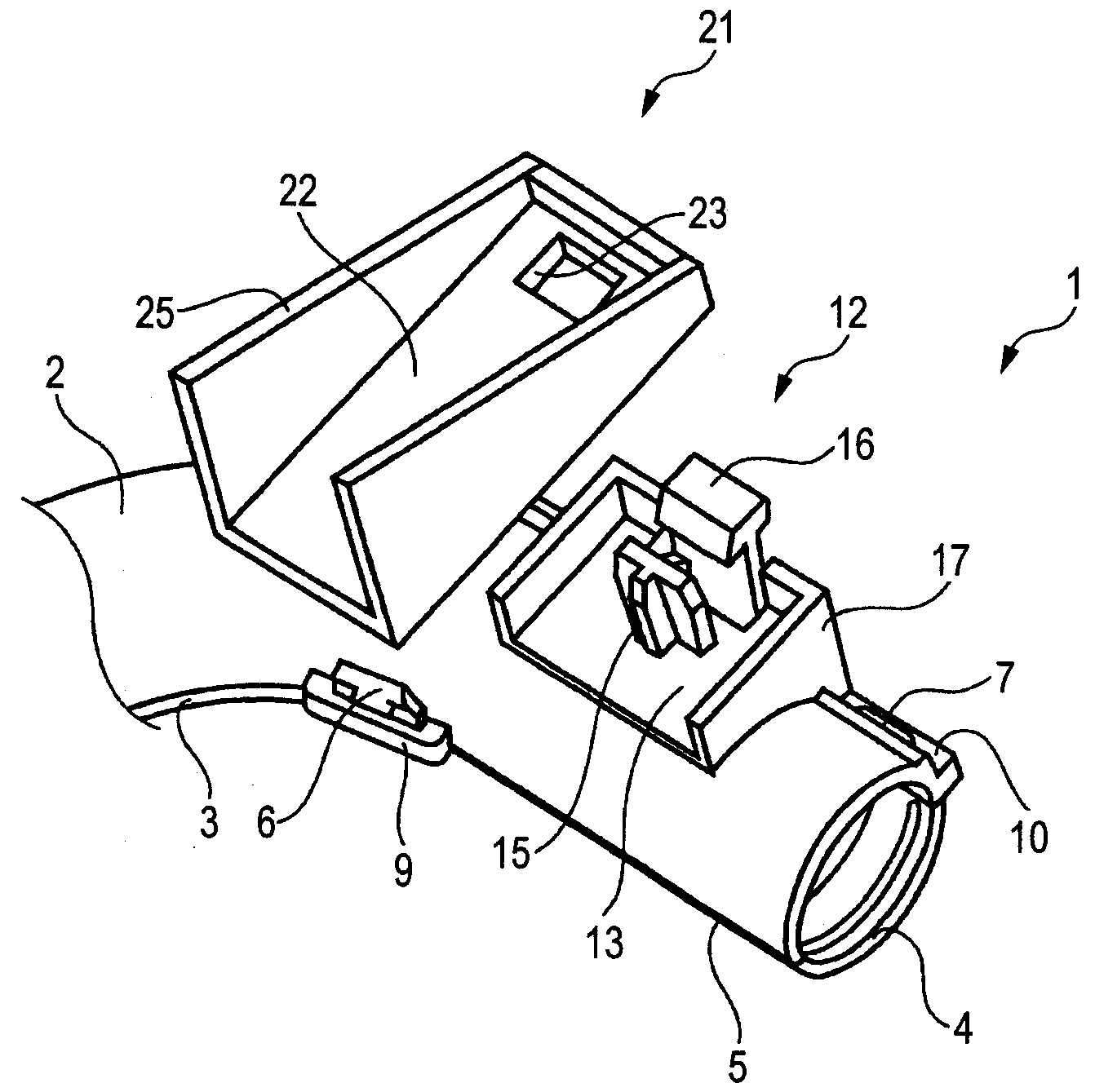
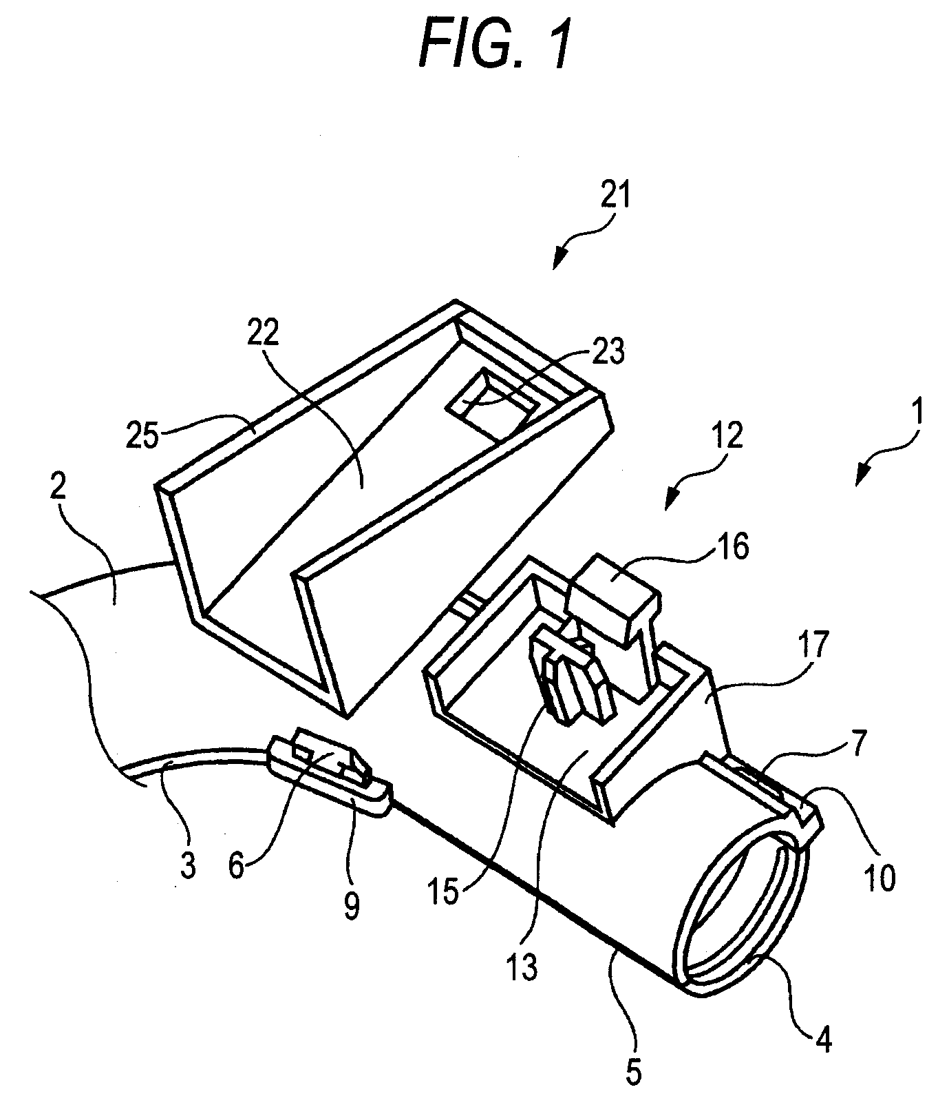
[0033]FIG. 1 is a perspective view showing a first embodiment of a protector of the present invention, FIG. 2 is a perspective view of a lock mechanism of the protector of FIG. 1, FIG. 3 is a plan view of the lock mechanism of FIG. 2, FIG. 4 is a plan view showing a vehicle-side stay, and FIG. 5 is a cross-sectional view showing a condition in which the protector of FIG. 1 is attached to the stay.

[0034]The protector 1 is an integrally-molded product made of a synthetic resin such as polypropylene and polyethylene, and this protector 1 includes a protector body 2 of a curved trough-shape as shown in FIG. 1. A first lid member 3 of an arcuate trough-shape is pivotally connected to the protector body 2 through a hinge (not shown), and a plurality of engagement claws 6 are formed on the first lid member 3. A plurality of engagement piece portions 9 are formed respectively at those portions of the protector body 2 corresponding respectively to the engagement claws 6. Further, a second li...

second embodiment

[0049]FIG. 6 is a perspective view showing a second embodiment of a protector of the invention, FIG. 7 is a perspective view of a lock mechanism of the protector of FIG. 6, FIG. 8 is a plan view of the lock mechanism of FIG. 7, FIG. 9 is a perspective view showing a condition in which the protector of FIG. 6 is attached to a stay. FIG. 10 is a cross-sectional view showing a condition in which the protector of FIG. 6 is attached to the stay.

[0050]The protector 1 is an integrally-molded product made of a synthetic resin such as polypropylene and polyethylene, and this protector 1 includes a protector body 2 of a curved trough-shape as shown in FIG. 6. A first lid member 3 of an arcuate trough-shape is pivotally connected to the protector body 2 through a hinge (not shown), and a plurality of engagement claws 6 are formed on the first lid member 3. A plurality of engagement piece portions 9 are formed respectively at those portions of the protector body 2 corresponding respectively to ...

third embodiment

[0065]FIG. 11 is a perspective view showing a third embodiment of a protector of the invention, and FIG. 12 is a plan view of the protector of FIG. 11.

[0066]Although the lock mechanism 12 of each of the above embodiments has the generally U-shaped frame portion 17 provided in an upstanding manner around the boss 15, the provision of the frame portion 17 can be omitted as shown in FIGS. 11 and 12. In this case, the frame portion 17 is not provided around the boss 15, and therefore only the boss passage hole 23 need to be formed through a predetermined portion of a vehicle side stay 21, and any other limitation is not imposed on the configuration of the stay 21. As a result, the versatility of the protector 1 is enhanced.

[0067]Further, a pair of shaking prevention ribs 18 having upper edges disposed flush with a stay abutment plate 13 may be formed on a protector body 2 as shown in FIGS. 11 and 12. In this case, when the protector 1 is attached to the stay 21, the areas of supporting ...


PUM


Abstract

In a protector, a lock mechanism for a stay is provided at a protector body. The lock mechanism includes a stay abutment plate which is perpendicular to a direction of a normal line of the protector body, a boss for passing through a boss passage hole in the stay, and a lock piece portion for locking the stay. With this construction, the amount of retaining engagement of the lock piece portion can be increased without adversely affecting the moldability of a mold. As a result, the force of retaining of the protector can be enhanced, thereby avoiding a situation in which the protector is disengaged from the stay.

Description

BACKGROUND OF THE INVENTION[0001]1. Field of the Invention[0002]This invention relates to a protector suitably used for installing a wire harness in a vehicle such as an automobile.[0003]2. Related Art[0004]FIG. 13 is a perspective view showing a conventional protector, and FIG. 14 is a cross-sectional view showing a condition in which the protector of FIG. 13 is attached to a stay.[0005]With respect to protectors of this kind, there has heretofore been proposed an attaching method (hereinafter referred to as “slide method”) in which the protector is slid to be engaged with a vehicle-side stay (see, for example, JP-A-9-84240 Publication). In this slide method, however, the protector can not be attached to the stay unless a sliding amount is not secured in a direction along a protector body.[0006]Therefore, in order that a protector can be attached even when a sliding amount can not be secured in a direction along a protector body, there is proposed a method (hereinafter referred to ...

Claims


Application Information

Patent Timeline
Patent Type & Authority Applications(United States)
IPC IPC(8): H02G3/04
CPCY10T24/42H02G3/0481
Inventor SUZUKI, MITSUHARUSONDA, SHINJIISHIMURA, YUUJIIHARA, TAKASHI
Owner YAZAKI CORP
Why Eureka
Try Eureka