Multi-functional regulator

a multi-functional, regulator technology, applied in the direction of fluid pressure control, process and machine control, instruments, etc., can solve the problems of inability to use prior art devices, and achieve the effect of reducing system integration effort, weight, complexity and cost, and reducing the number and size of individual components

Inactive Publication Date: 2008-01-31
STANDFORD MU
View PDF14 Cites 40 Cited by
  • Summary
  • Abstract
  • Description
  • Claims
  • Application Information

AI Technical Summary

Benefits of technology

[0012]The presently described apparatus is a multi-functional regulator (MFR) and control valve integrating the isolation and regulation functions of gas flow control systems into a single, compact device. The MFR serves as both a fail safe closed shutoff valve and a regulator, which is not possible in prior art devices. It is configured to return to a closed state should electrical power be lost, which is the desired “fail safe” state in virtually all aerospace system applications. The MFR consists of a pneumatic dome loaded regulator having: sensing element (including but not limited to a diaphragm, bellows or piston), sensing orifice, control chamber, poppet and seat, poppet spring, push pin and main spring, with added elements to enable electronic control, including: inlet pressure sensor, control chamber pressure sensor, a feedback (pressure, mass flow, or temperature) sensor, two electromagnetic operated pilot valves, and an electronic controller. The MFR provides pressure regulation, isolation, mass flow control, local or remote sensing, adjustable set point, and slam-start avoidance. Plural MFR's are arrange to provide fail-safe operation. The MFR is an integrated solution that substantially reduces the number and size of individual components in a system, greatly reducing system integration effort, weight, complexity and cost.

Problems solved by technology

The MFR serves as both a fail safe closed shutoff valve and a regulator, which is not possible in prior art devices.

Method used


Image

  • Multi-functional regulator
  • Multi-functional regulator
  • Multi-functional regulator

Examples


Embodiment Construction

[0021]The above described drawing figures illustrate the described apparatus and its method of use in at least one of its preferred, best mode embodiment, which is further defined in detail in the following description. Those having ordinary skill in the art may be able to make alterations and modifications to what is described herein without departing from its spirit and scope. Therefore, it must be understood that what is illustrated is set forth only for the purposes of example and that it should not be taken as a limitation in the scope of the present apparatus and method of use.

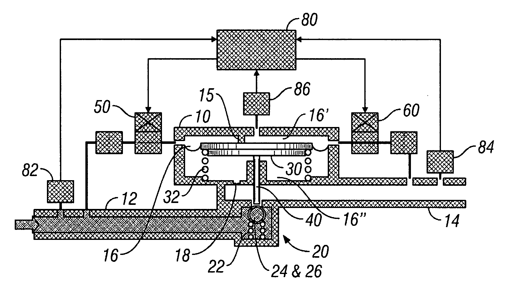
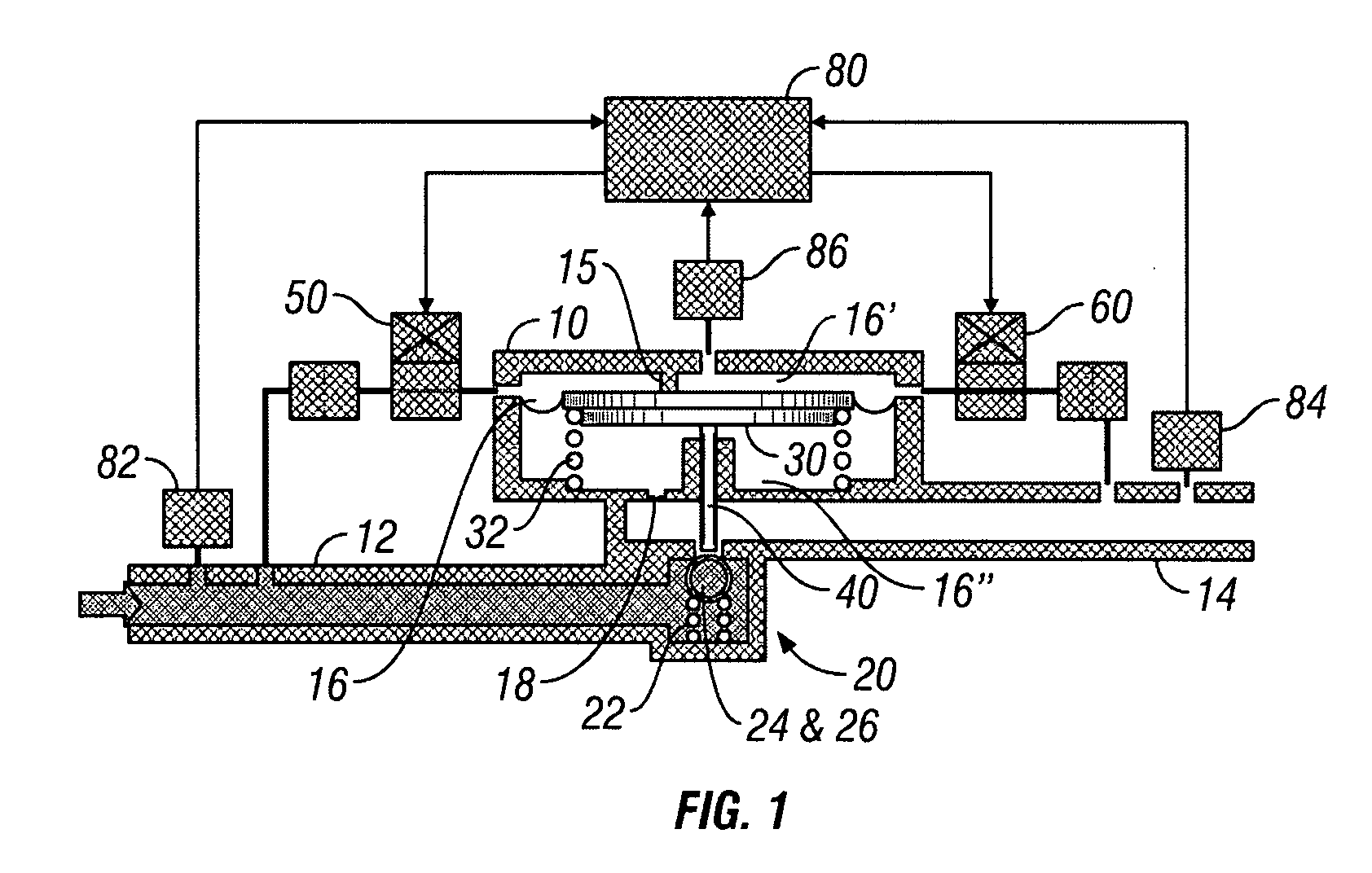
[0022]As shown in FIG. 1, the present multifunctional fluid control apparatus comprises a housing 10 providing integral portions including an inlet passage 12 joined with an outlet passage 14 through a poppet valve 20. A linearly movable control diaphragm 30 is biased to a nominal position by a main spring 32 within a control chamber 16, and separates the control chamber 16 into a first volume 16′, often...


PUM


Abstract

A multifunctional regulator provides a housing having an inlet passage joined with an outlet passage through a poppet valve. The housing has a control diaphragm separating the control chamber into a first volume and a second volume and depending on the differential pressure between the two volumes, the diaphragm will push open the poppet valve. Pressurizing and depressurizing valves join the first volume with the inlet and outlet passages, whereby, with an inlet pressure level within the inlet passage greater than an outlet pressure level within the outlet passage, and with the pressurizing valve admitting the inlet pressure level to the first volume, the diaphragm is displaced into the second volume thereby forcing the poppet valve to open and thereby raising the outlet pressure toward the inlet pressure with fluid flow from the inlet to outlet passages.

Description

CROSS-REFERENCE TO RELATED APPLICATIONS[0001]This application claims priority of a prior filed and concurrently pending Provisional Patent Application having Ser. No. 60 / 696,814 and filing date Jul. 7, 2005, and which is incorporated herein by reference.STATEMENT REGARDING FEDERALLY SPONSORED RESEARCH OR DEVELOPMENT[0002]Not applicable.THE NAMES OF THE PARTIES TO A JOINT RESEARCH AGREEMENT[0003]Not applicable.INCORPORATION-BY-REFERENCE OF MATERIAL SUBMITTED ON A COMPACT DISC[0004]Not applicable.REFERENCE TO A “MICROFICHE APPENDIX”[0005]Not applicable.BACKGROUND OF THE INVENTION[0006]1. Field of the Present Disclosure[0007]This disclosure relates generally to electronically enhanced mechanical fluid control devices and more particularly to a multifunctional device having fluid shutoff valve function as well as adjustable fluid regulator function; and to failsafe operation of such device using series and parallel arrangement redundancy.[0008]2. Description of Related Art Including Inf...

Claims


Application Information

Patent Timeline
Patent Type & Authority Applications(United States)
IPC IPC(8): F16K31/12
CPCF16K15/183G05D16/163F16K31/402F16K31/128F16K15/1823Y10T137/7761Y10T137/7762
Inventor REINICKE, ROBERT H.CHOW, PETER C. M.
Owner STANDFORD MU
Why Eureka
Try Eureka