
Image processing device and printing apparatus for performing bidirectional printing

a technology of image processing device and printing apparatus, applied in the field of dots, can solve the problems of no approach of organically combining these two image quality-improving techniques, and achieve the effect of improving image quality

Inactive Publication Date: 2008-01-31
SEIKO EPSON CORP
View PDF16 Cites 6 Cited by
  • Summary
  • Abstract
  • Description
  • Claims
  • Application Information

AI Technical Summary

Benefits of technology

[0006]An advantage of some aspect of the invention is to provide a technique that organically combines the halftone process with the formation control of ink dots to further improve the image quality.
[0007]The invention provides a printing method of performing printing on a print medium. The method includes: generating dot data representing a status of dot formation on each of print pixels of a print image to be formed on the print medium, by performing a halftone process on image data representing a input tone value of each of pixels constituting an original image; generating the print image by combining forward pass dots with backward pass dots in a common printing area in such a manner that each main scan line includes both the forward pass dots and the backward pass dots, the forward pass dots being formed on a plurality of pixels of a first pixel group in a forward pass of main scan of a print head, the backward pass dots being formed on a plurality of pixels of a second pixel group in a backward pass of main scan of the print head. The generating dot data includes setting a halftone process condition for reducing a deterioration of image quality due to a positional misalignment between the forward pass dots formed in the first pixel group and the backward pass dots formed in the second pixel group.
[0008]In the printing method of the invention, the condition of the halftone process is set to reduce the potential deterioration of the image quality due to the positional misalignment between the forward pass dots formed in the forward pass of the print head and the backward pass dots formed in the backward pass of the print head. Each main scan line consists of both the forward pass dots and the backward pass dots. This arrangement effectively reduces the graininess, the uneven color, and the banding and thereby totally improves the image quality.
[0010]One applicable procedure individually performs error diffusion in each of multiple different pixel position groups, in addition to the general overall error diffusion. Another applicable procedure increases the weight to be applied to a diffused error in each of pixels included in plural different pixel position groups. The inherent features of the error diffusion technique enable all dot patterns formed in print pixels included in the respective pixel position groups to have specific characteristics at each tone value.
[0011]In one aspect of the printing apparatus of the invention, the printing structure is set to have a greater consecutive number of either the forward pass dots or the backward pass dots in a sub-scanning direction than a consecutive number of the corresponding dots in a main scanning direction. As confirmed by the inventors' experiments, this arrangement enhances the banding prevention effect.

Problems solved by technology

However, the improved image quality by the halftone process and the improved image quality by the adequate formation control of ink dots have been studied and discussed as individually different technical issues in the art.
There has been no approach of organically combining these two image quality-improving techniques to attain the synergistic effects on improvement of image quality.

Method used


Image

  • Image processing device and printing apparatus for performing bidirectional printing
  • Image processing device and printing apparatus for performing bidirectional printing
  • Image processing device and printing apparatus for performing bidirectional printing

Examples


Embodiment Construction

[0038]The present invention is explained in the following sequence based on embodiments.

A. Summary of the Embodiment:

B. Device Constitution:

C. Summary of the Image Printing Process:

[0039]D. Principle of Suppressing Degradation of Image Quality Due to Dot Position misalignment:

E. Dither Matrix Generating Method:

F. Variation Examples:

A. Summary of the Embodiments

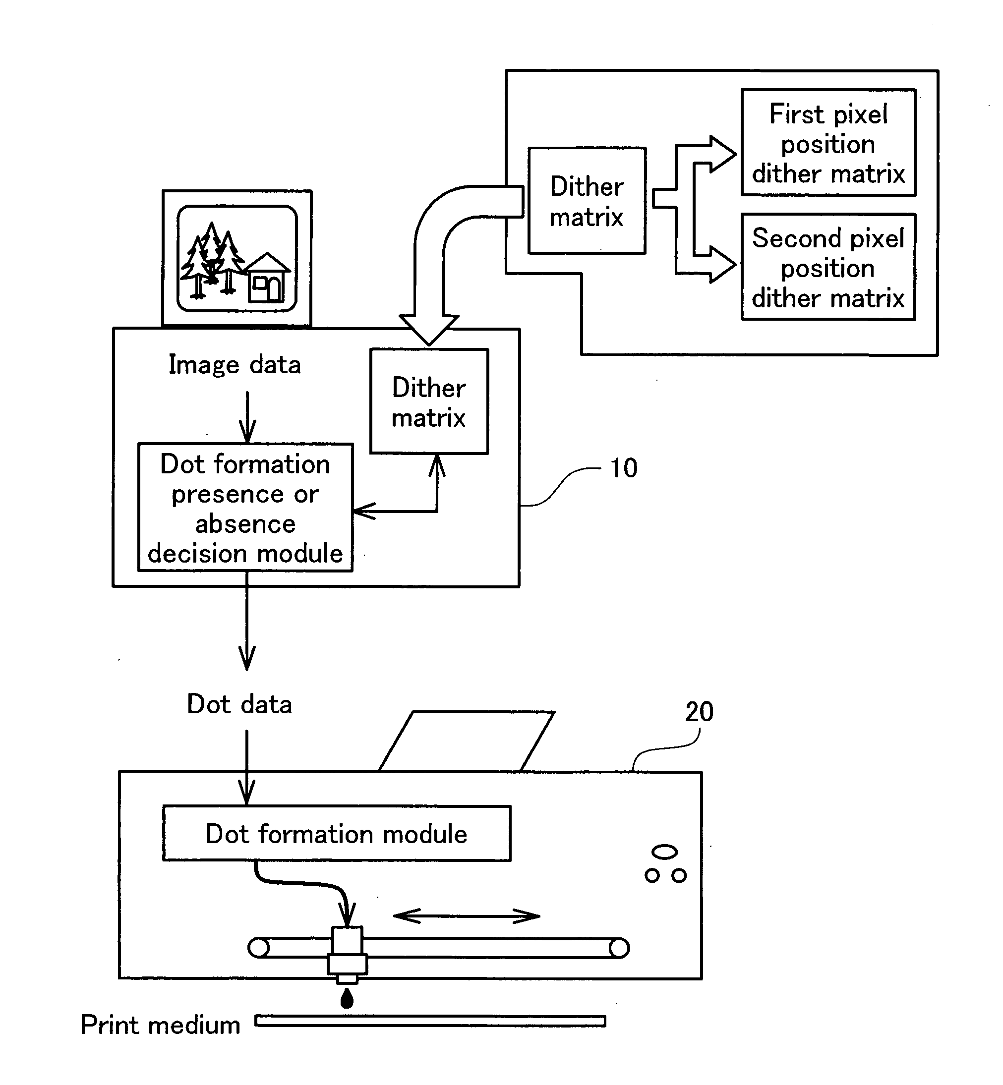
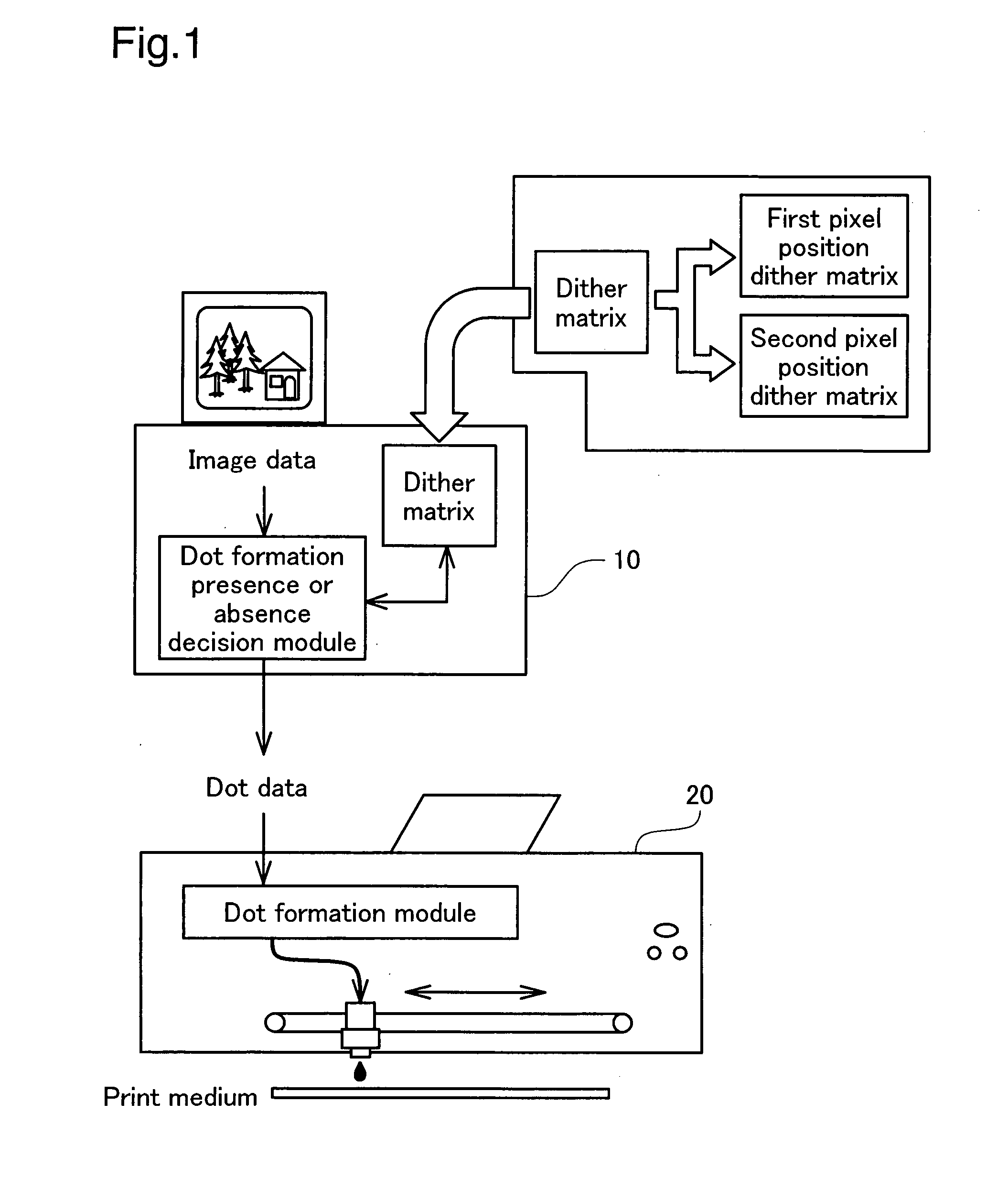
[0040]Before starting the detailed description of the embodiment, a summary of the embodiment is described while referring to FIG. 1. FIG. 1 is an explanatory drawing showing a summary of a printing system as the printing apparatus of this embodiment. As shown in the drawing, the printing system consists of a computer 10 as the image processing device, a printer 20 that prints the actual images under the control of the computer 10 and the like, and entire system is unified as one and functions as a printing apparatus.

[0041]A dot formation presence or absence decision module and a dither matrix are provided in the computer 10, ...


PUM


Abstract

The invention provides a printing method of performing printing on a print medium. The method includes: generating dot data representing a status of dot formation on each of print pixels of a print image to be formed on the print medium, by performing a halftone process on image data representing a input tone value of each of pixels constituting an original image; generating the print image by combining forward pass dots with backward pass dots in a common printing area in such a manner that each main scan line includes both the forward pass dots and the backward pass dots, the forward pass dots being formed on a plurality of pixels of a first pixel group in a forward pass of main scan of a print head, the backward pass dots being formed on a plurality of pixels of a second pixel group in a backward pass of main scan of the print head. The generating dot data includes setting a halftone process condition for reducing a deterioration of image quality due to a positional misalignment between the forward pass dots formed in the first pixel group and the backward pass dots formed in the second pixel group.

Description

BACKGROUND[0001]1. Technical Field[0002]The present invention relates to a technique of forming dots on a print medium to generate a print image.[0003]2. Related Art[0004]Inkjet printers have been used widely as the output device of computers. Various techniques, for example, the improved error diffusion or another halftone technique and the adequate formation control of ink dots (adjustment of the dot formation order) have been proposed for the inkjet printers to improve the image quality as disclosed in JP-A-2002-11859.[0005]However, the improved image quality by the halftone process and the improved image quality by the adequate formation control of ink dots have been studied and discussed as individually different technical issues in the art. There has been no approach of organically combining these two image quality-improving techniques to attain the synergistic effects on improvement of image quality.SUMMARY[0006]An advantage of some aspect of the invention is to provide a tec...

Claims


Application Information

Patent Timeline
Patent Type & Authority Applications(United States)
IPC IPC(8): G06K15/00H04N1/40
CPCH04N1/4051
Inventor KAKUTANI, TOSHIAKIYAMAZAKI, SATOSHITANASE, KAZUYOSHITAKAHASHI, TORU
Owner SEIKO EPSON CORP
Learn More