Machine tool comprising a protective cabinet and an illumination system

a technology of illumination system and protective cabinet, which is applied in the direction of manufacturing tools, lighting and heating apparatus, lighting applications, etc., can solve the problem of limited selection of positioning positions, and achieve the effect of reducing the interior space of the protective cabin

Active Publication Date: 2008-01-31
DECKEL MAHO PFRONTEN GMBH
View PDF8 Cites 12 Cited by
  • Summary
  • Abstract
  • Description
  • Claims
  • Application Information

AI Technical Summary

Benefits of technology

[0010] To avoid a reduction of the interior space of the protective cabinet the flat lamps according to the invention may also be installed in indentations in one or more cabinet walls or in the cabinet ceiling, a permanent sealing being required in that case.

Problems solved by technology

Due to the dimensions of the built-in lamps the selection of their positioning is limited since only certain positions in the respective workspace within the protective cabinet are suitable for placing and mounting such elongated lighting elements.

Method used


Image

  • Machine tool comprising a protective cabinet and an illumination system
  • Machine tool comprising a protective cabinet and an illumination system

Examples


Embodiment Construction

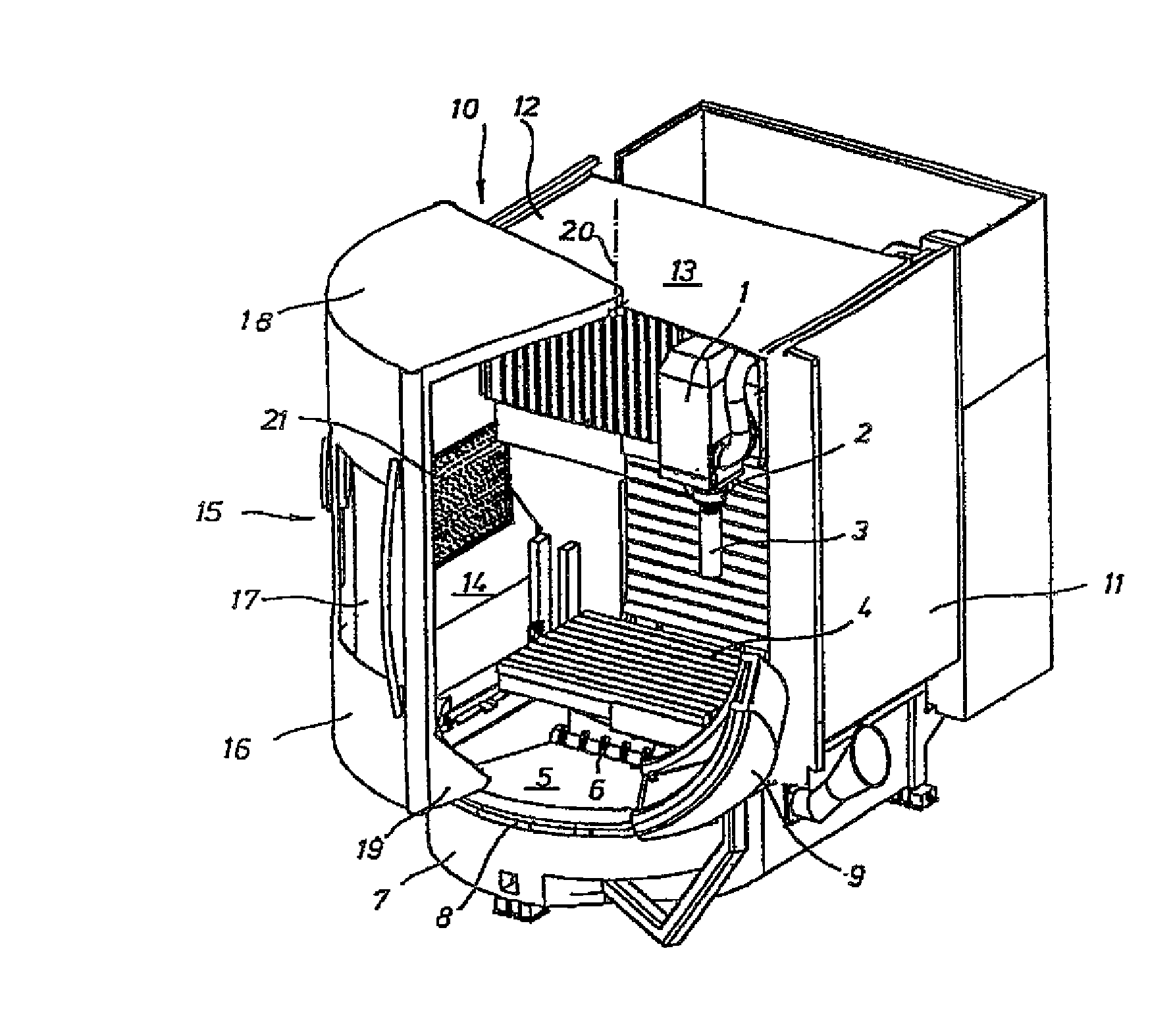
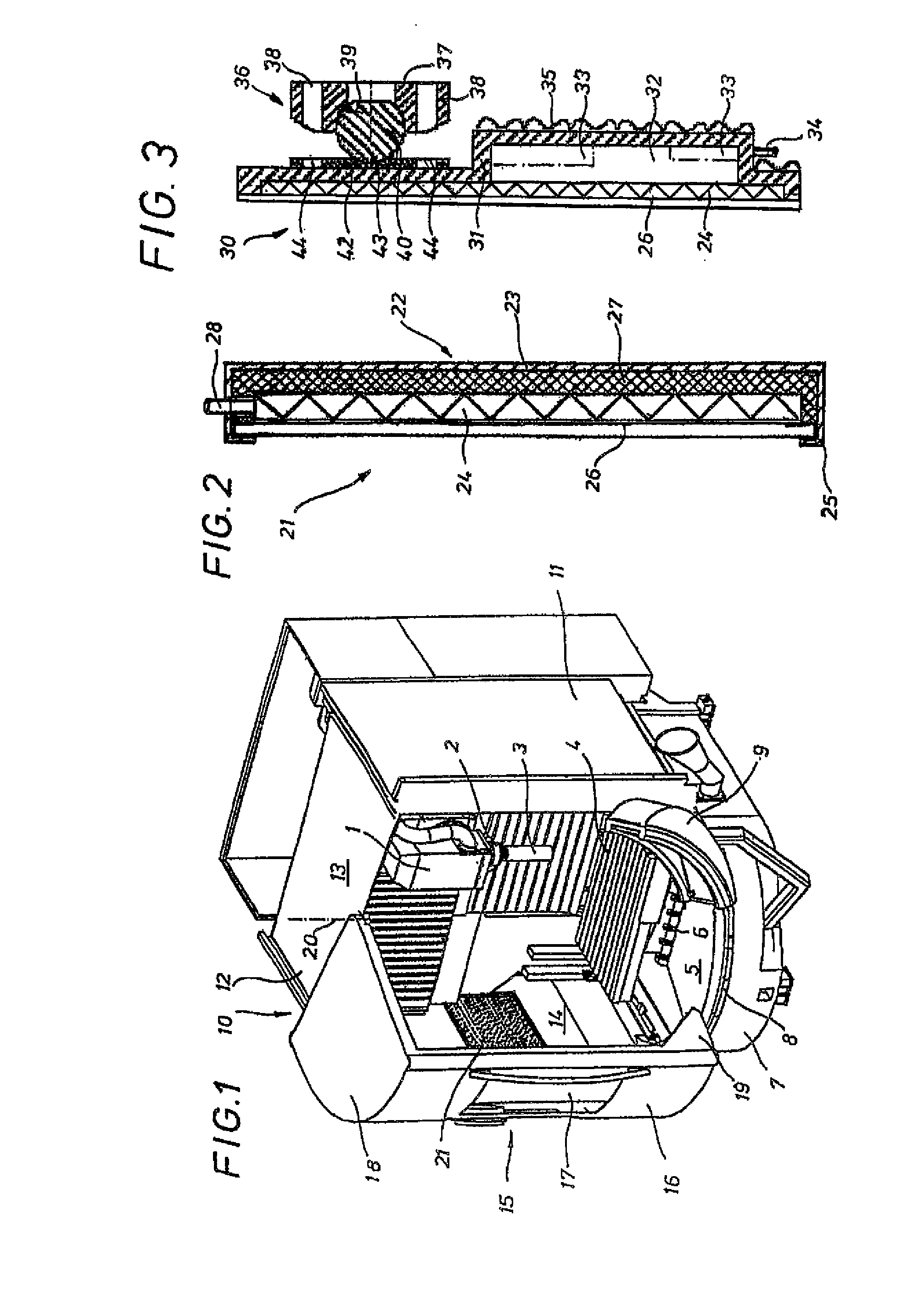
[0016]FIG. 1 shows a program controlled milling and drilling machine which is only to be regarded as an example for an efficient arrangement of a flat lamp. The machine tool comprises machining head 1 which is shiftable on a column along two horizontal coordinate axes by means of a motor, a tool 3 being clamped in vertical work spindle 2 of the machining head. Workpiece table 4 is supported by a panel shiftable along the vertical coordinate axis on the front side of the machine column by means of a motor. The table surface defines the maximum workspace. Rotating spindle 6 for chip discharge is disposed in half-round bottom pan 5 below workpiece table 4. Toward the front side, bottom pan 5 is limited by a half-round face 7 carrying a guide rail 8 displaced downwardly on its outer side.

[0017] Protective cabinet 10 consists of two rear side walls 11, 12, covering wall 13 connected between the side walls, and front side wall 14 extending a distance from workpiece table 4 and laterally ...


PUM

PropertyMeasurementUnit
thicknessaaaaaaaaaa
heightaaaaaaaaaa
luminous intensityaaaaaaaaaa

Abstract

A machine tool having a protective cabinet and an illumination system comprising at least one discharge lamp installed in the interior space of the protective cabinet. The discharge lamp is formed as a flat lamp radiating over a large area with a uniform luminous intensity and disposed on a cabinet wall in order to obtain an enhanced illumination of the entire workspace of the machine as well as of the interior space of the protective cabinet.

Description

FIELD OF THE INVENTION [0001] The invention relates generally to a machine tool comprising a protective cabinet and an illumination system comprising at least one discharge lamp installed in the interior space of the protective cabinet. DISCUSSION OF PRIOR ART [0002] Modern machine tools and machining centers regularly comprise a protective cabinet surrounding the workspace and, where required, also surrounding the secondary devices during operation. To enable access to the workspace sliding doors are provided which are movable rectilinearly or on round guides. The side walls as well as the sliding doors comprise viewing windows in respectively suitable arrangements and sizes in order to enable an observation of the operation and the progress of the work. For work within the workspace with the sliding doors opened as well as for monitoring the operating cycles, one or, in most cases, a plurality of lamps are provided at suitable positions of the inner wall of the protective cabinet,...

Claims


Application Information

Patent Timeline
Patent Type & Authority Applications(United States)
IPC IPC(8): F21V33/00B23Q11/08B23Q17/24
CPCB23Q11/0891B23Q17/2404Y10T409/30392F21Y2105/00F21W2131/403
Inventor SEITZ, REINHOLDHAGIN, JOSEF
Owner DECKEL MAHO PFRONTEN GMBH
Why Eureka
Try Eureka