Light-emitting heat-dissipating device and manufacturing method thereof

a heat dissipating device and heat dissipation technology, which is applied in the direction of semiconductor devices for light sources, lighting and heating apparatus, and light support devices, etc., can solve the problems of ineffective heat dissipation, limited power of led package modules, and direct influence on reliability and lifetime of electronic elements, so as to improve heat dissipation efficiency of light-emitting heat dissipation devices, and improve heat dis

Inactive Publication Date: 2008-01-31
DELTA ELECTRONICS INC
View PDF6 Cites 16 Cited by
  • Summary
  • Abstract
  • Description
  • Claims
  • Application Information

AI Technical Summary

Benefits of technology

[0015]As mentioned above, compared with the prior art, the invention can transfer the heat from the heat end of the thermally conducting element to the cold end of the thermally conducting element to dissipate the heat. This method can dissipate the heat of the light-emitting package module more effectively

Problems solved by technology

Therefore, the heat dissipating efficiency directly influences the reliability and the lifetime of the electronic element.
Thus, the power of the LED package module is limited to about 0.1 watt.
However, when the LED package module 1 is used for a long time, the lead frame 13 cannot effectively dissipate the heat, and the accumulated heat influen

Method used


Image

  • Light-emitting heat-dissipating device and manufacturing method thereof
  • Light-emitting heat-dissipating device and manufacturing method thereof
  • Light-emitting heat-dissipating device and manufacturing method thereof

Examples


Embodiment Construction

[0028]The present invention will be apparent from the following detailed description, which proceeds with reference to the accompanying drawings, wherein the same references relate to the same elements.

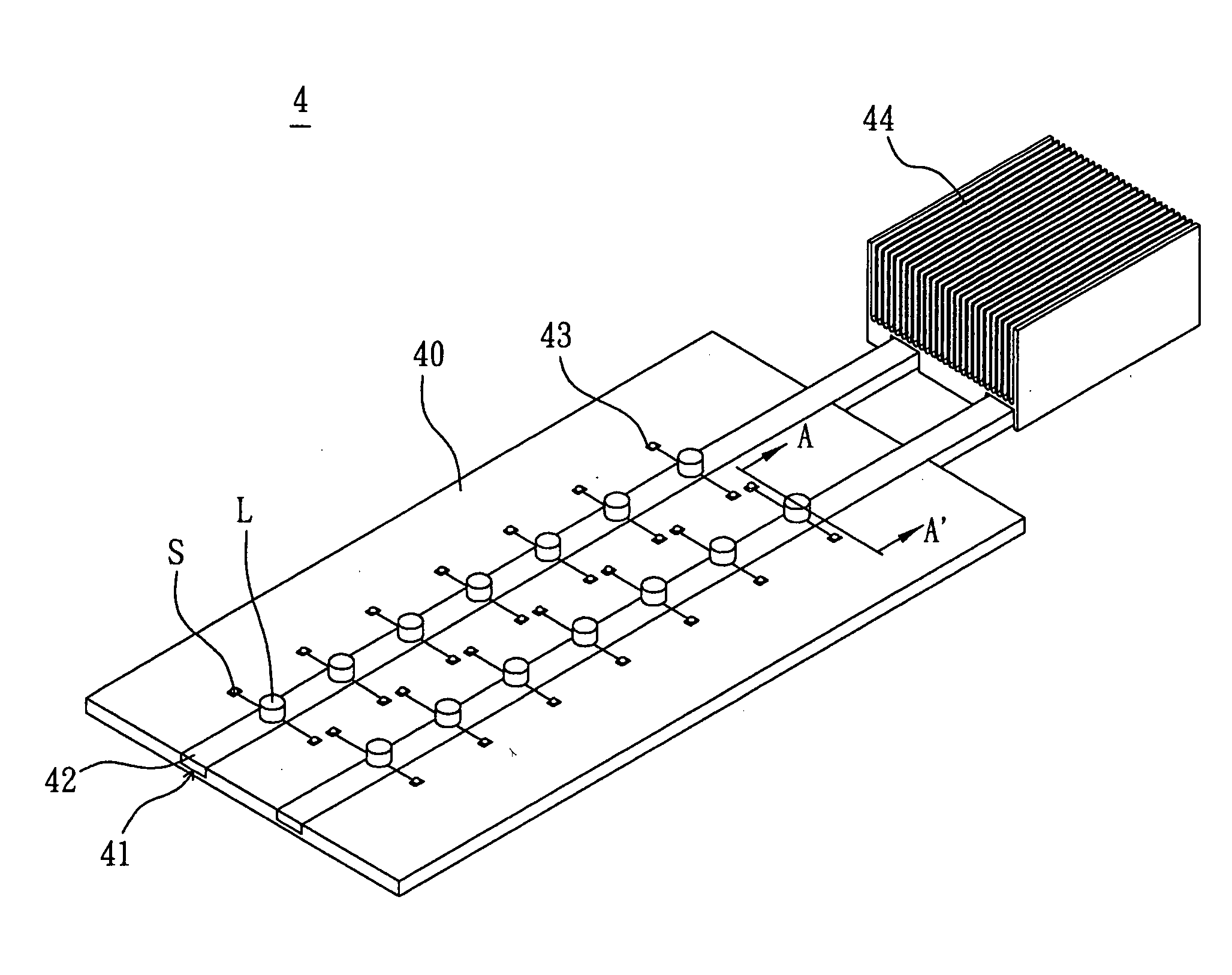
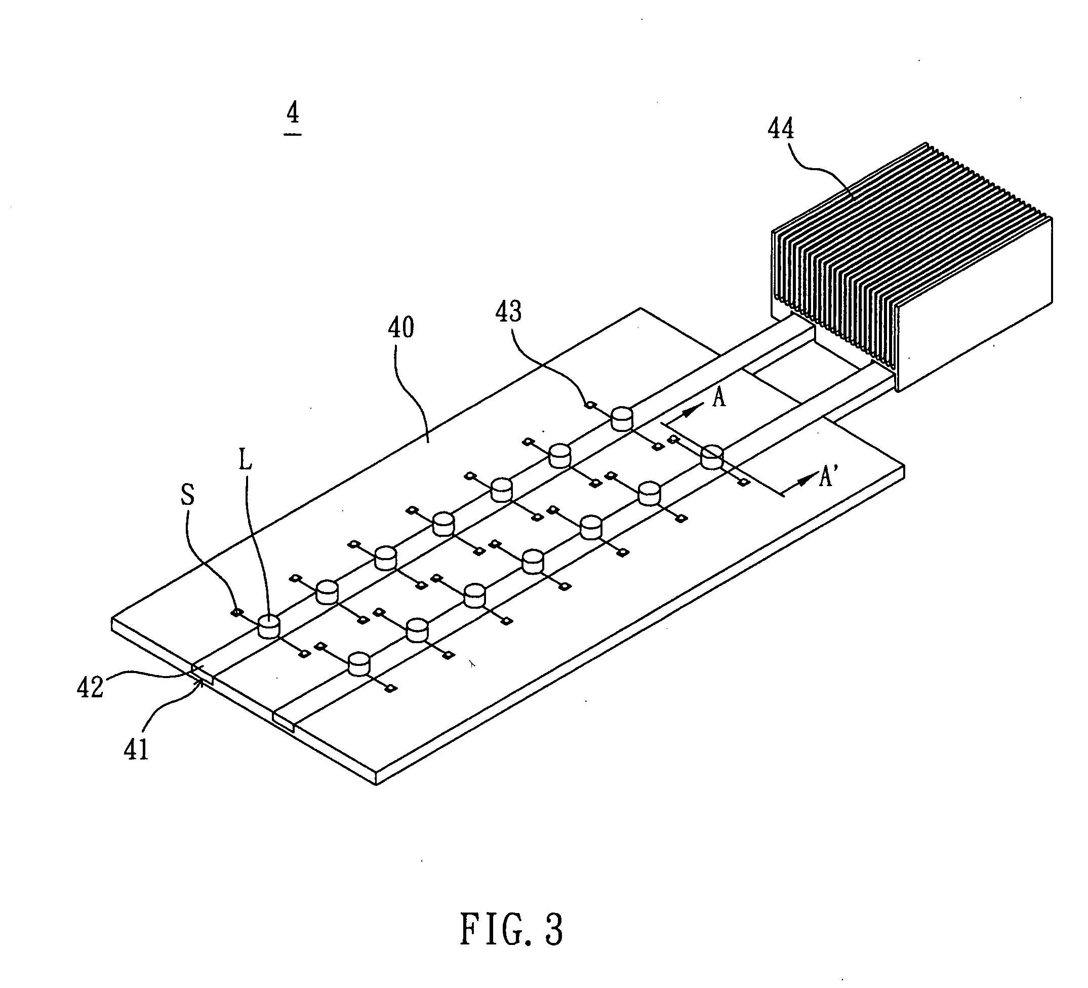
[0029]Referring to FIGS. 3 and 4, a light-emitting heat-dissipating device 4 according to an embodiment of the invention includes at least one light-emitting package module L and a substrate 40. The substrate 40 has at least one recess 41 and at least one thermally conducting element 42 disposed in the recess 41. The light-emitting package module L is disposed on the thermally conducting element 42. In this embodiment, the substrate 40 has a plurality of thermally conducting elements 42, and a plurality of light-emitting package modules L is disposed on each thermally conducting element 42.

[0030]The substrate 40 is not particularly restricted and may be a typical printed circuit board (PCB) or a low-temperature co-fired ceramic (LTCC) circuit board. The substrate 40 has a circuit layo...


PUM

PropertyMeasurementUnit
Temperatureaaaaaaaaaa
Electrical conductoraaaaaaaaaa
Heataaaaaaaaaa

Abstract

A light-emitting heat-dissipating device includes a substrate and at least a light-emitting package module capable of generating heat. The substrate includes at least a recess and at least one thermally conducting element disposed in the recess. The light-emitting package module is disposed on the thermally conducting element and electrically connected to the substrate of the substrate via solder joints. A manufacturing method of the light-emitting heat-dissipating device is also disclosed.

Description

CROSS REFERENCE TO RELATED APPLICATIONS[0001]This Non-provisional application claims priority under 35 U.S.C. §119(a) on Patent Application No(s). 095127658 filed in Taiwan, Republic of China on Jul. 28, 2006, the entire contents of which are hereby incorporated by reference.BACKGROUND OF THE INVENTION[0002]1. Field of Invention[0003]The invention relates to a light-emitting heat-dissipating device and a manufacturing method thereof, and, in particular, to a light-emitting heat-dissipating device for dissipating heat using a heat pipe and a manufacturing method thereof.[0004]2. Related Art[0005]Due to the progress of the technology, various electronic products need to have more and more functions. In addition to the continuous upgrade of the speed of the desktop computer, portable mobile electronic devices, such as personalized products including a notebook computer, a mobile phone, a mini CD and a hand-held computer, have become the important trend of the development. However, as t...

Claims


Application Information

Patent Timeline
IPC IPC(8): F21V29/00H05K3/34
CPCH01L2224/48091Y10T29/49144H01L2224/48247H05K2201/10416F21V29/004F21V29/006F21V29/2212F21Y2101/02H05K1/0204H05K1/0306H05K3/0061H05K3/3421H05K2201/09036H05K2201/09745H05K2201/10106H01L2924/00014H01L2924/12044F21Y2115/10F21V29/508F21V29/51H01L2924/00
Inventor HSIEH, YU-PINGLEE, YI-SHENGCHENG, CHIN-MINGYU, CHIH-HAOCHANG, YU-CHINGHUANG, YI-HONG
Owner DELTA ELECTRONICS INC
Why Eureka
Try Eureka