
Coherent optical transceiver and coherent communication system and method for satellite communications

a technology of optical transceivers and coherent communication systems, applied in electromagnetic transceivers, satellite communication transmission, transmission monitoring, etc., can solve problems such as x-ray degrade the performance of electro-optical devices in space, patents did not explore signal corruption, and microwave satellite communication links with data rates of about 500 mb/s do not possess enough capacity to meet the increasing data transmission demand. , to achieve the effect of fast elimination of additive nois

Inactive Publication Date: 2008-01-31
CELIGHT
View PDF10 Cites 29 Cited by
  • Summary
  • Abstract
  • Description
  • Claims
  • Application Information

AI Technical Summary

Benefits of technology

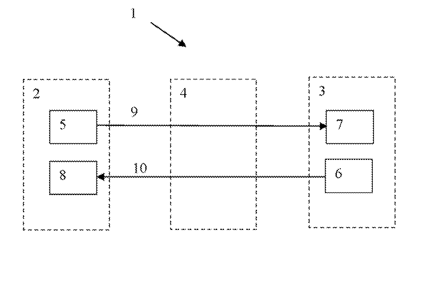
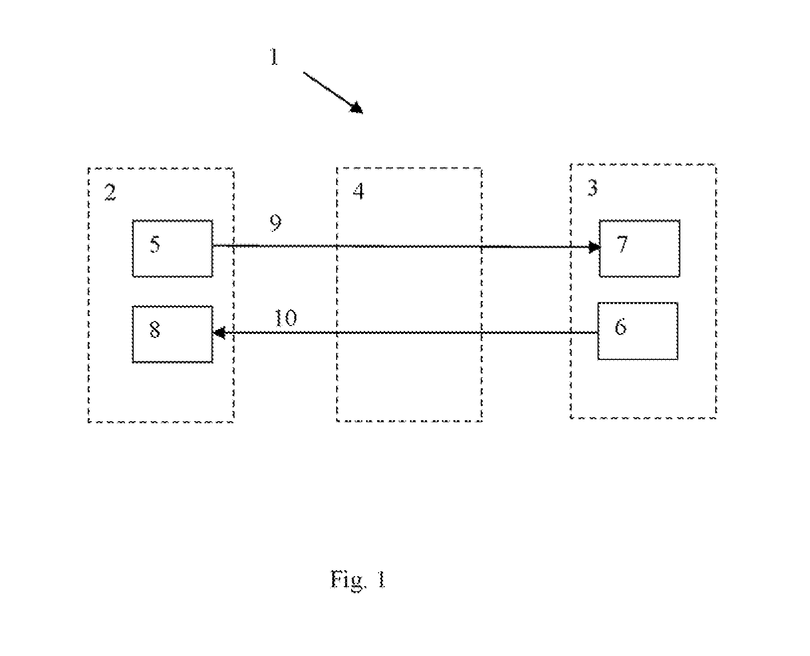
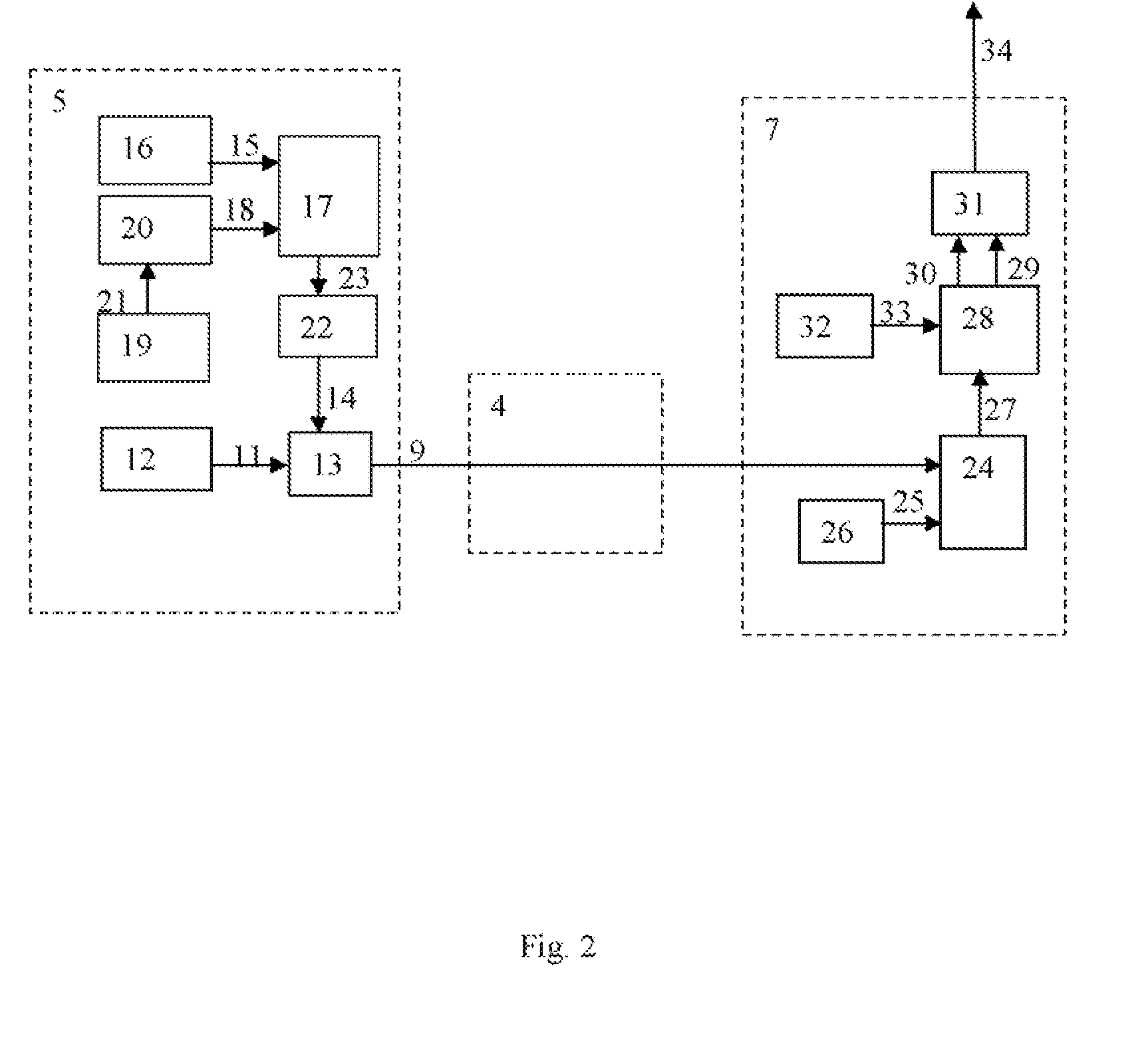
[0009] The system and method are disclosed for the additive noise cancellation, which is typically a vibration noise, caused by moving platform, where the transceiver is located. Data transmission from one location to another is performed using PSK modulation format. In the preferred embodiment QPSK or QAM modulation is applied. The signal correction is applied both to the transmitter and to the receiver side. A first means located on the receiver platform measures an additive phase noise and provides a correcting signal. The receiver comprises a digital signal processing (DSP) unit for fast elimination of additive noise in the signal basing on the correcting signal.

Problems solved by technology

Microwave satellite communication links with data rate of about 500 Mb / s does not possess enough capacity to meet the increasing data transmission demand.
However those patents did not explore the signal corruption caused by the additive phase-noise resulting from vibration onboard the satellite.
It is well known ionizing radiation, such as cosmic rays, gamma rays, and hard X-rays degrade electro-optical device performance in space.

Method used


Image

  • Coherent optical transceiver and coherent communication system and method for satellite communications
  • Coherent optical transceiver and coherent communication system and method for satellite communications
  • Coherent optical transceiver and coherent communication system and method for satellite communications

Examples


Embodiment Construction

[0020] The present invention is now described more fully with reference to the accompanying figures, in which some of all possible embodiments of the invention are shown. The present invention may be embodied in various forms and should not be viewed as limited to the embodiments set forth herein. Rather these embodiments are provided so that this disclosure will be thorough and complete and will fully disclose the invention to those skilled in the art.

[0021] The invention primarily addresses communication links with phase shift keying data modulation format, namely binary phase shift keying (BPSK), quadrature phase shift keying (QPSK), M-ary phase shift keying (M-PSK), M-ary quadrature amplitude modulation (M-QAM). These modulation formats considered to be the most promising in the next generation of optical communication in free space, intersatellite, ground-satellite, submarine or terrestrial fiber links.

[0022] The invention is not limited to phase modulated optical communicati...


PUM


Abstract

An optical transceiver is provided for optical communications with additive noise compensation. The system and method are disclosed for the additive noise cancellation, which is typically a vibration noise, caused by moving platform, where the transceiver is located. The transceiver comprises an additive noise sensor and a digital signal processing (DSP) unit which implements variable step size technique to adjust the filter weight in the least square estimate of the noise signal. In the preferred embodiment the digital signal processing is applied both at the transmission and the receiving side. The optical device is packed for ground-satellite and inter-satellite communications applications with resistance to high-energy X-rays, gamma rays and cosmic rays. The optical device sustains its operation characteristics under launch load.

Description

CROSS-REFERENCE TO RELATED APPLICATIONS [0001] This application claims priority to U.S. provisional application Ser. No. 60 / 850,085 filed Oct. 6, 2006. This application is a continuation-in-part of U.S. patent application Ser. No. 10 / 669,130 filed Sep. 22, 2003 and is also a continuation-in-part of U.S. patent application Ser. No. 10 / 613,772 filed Jul. 2, 2003, U.S. patent application Ser. No. 11 / 610,964 filed Dec. 14, 2006 and U.S. patent application Ser. No. 11 / 672,372 filed Feb. 7, 2007 all of which applications are fully incorporated herein by reference.FIELD OF INVENTION [0002] This invention relates generally to optical systems and methods used in optical satellite communications and in some other optical systems suffering from hard radiation and various types of vibration and noises. In particular the invention addresses systems that implement coherent optical detection technique combined with digital signal processing for vibration noise reduction. BACKGROUND OF THE INVENTIO...

Claims


Application Information

Patent Timeline
Patent Type & Authority Applications(United States)
IPC IPC(8): H04B10/00
CPCH04B10/118H04B10/61H04B10/40
Inventor SHPANTZER, ISAACKAZI, SABERA
Owner CELIGHT
Learn More