Sound source separation apparatus and sound source separation method

a separation apparatus and sound source technology, applied in the field of sound source separation apparatus and sound source separation, can solve the problems of unpractical, unsuitable for real-time process, and the total delay time becomes 242 [msec], and achieves high sound source separation performance, and shortening the time of output delay

Inactive Publication Date: 2008-01-31
KOBE STEEL LTD
View PDF1 Cites 7 Cited by
  • Summary
  • Abstract
  • Description
  • Claims
  • Application Information

AI Technical Summary

Benefits of technology

[0068]According to the present invention, by setting the execution cycle (the above-described second time t2) for the Fourier transform for obtaining the second frequency-domain signal used as the input signal of the filter process (the process of the second Fourier transform unit) sufficiently short, it is possible to significantly shorten the time of the output delay as compared with the conventional case.
[0069]Furthermore, the execution cycle (the above-described first time

Problems solved by technology

However, the TDICA method requires an extremely complicated (high operational load) process for the learning computation of the separating matrix (a process for a convolutive mixture) and therefore is not suitable to a real time process.
Therefore, in the conventional sound source separation process, there is a problem in that the output delay equivalent to the time length of the next signal by the 3N samples is caused in total.
When the sound source separation based on the conventional FDICA method is applied to this digital mobile phone, the total delay time becomes 242 [msec], which is unpractical.
In a

Method used


Image

  • Sound source separation apparatus and sound source separation method
  • Sound source separation apparatus and sound source separation method
  • Sound source separation apparatus and sound source separation method

Examples


first embodiment (refer to figs.1 and 2)

First Embodiment (Refer to FIGS. 1 and 2)

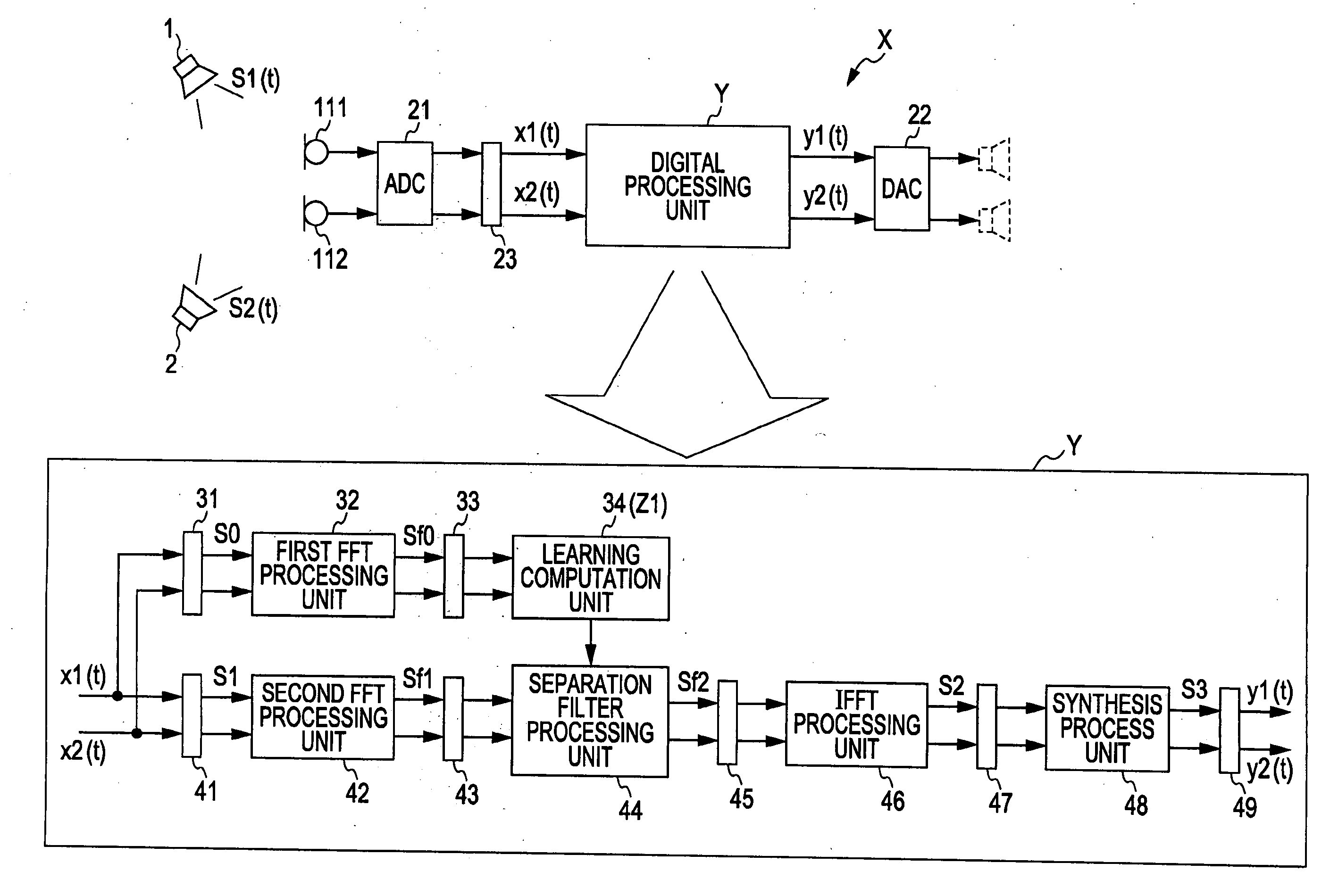
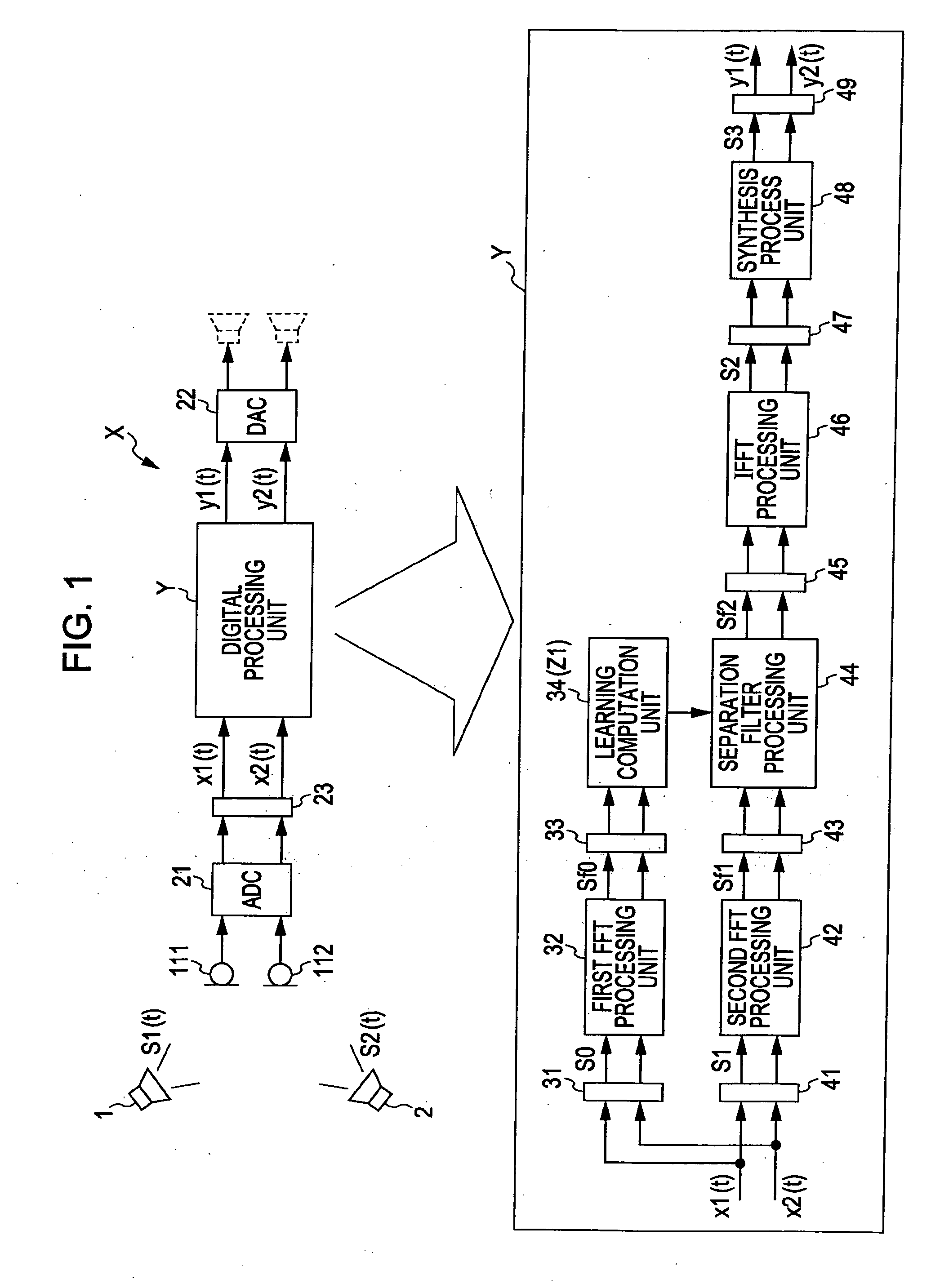
[0087]Hereinafter, with reference to a block diagram illustrated in FIG. 1, a description will be given of a sound source separation apparatus X according to an embodiment of the present invention. It should be noted that the following embodiment is an example that embodies the present invention, and does not have a nature of limiting the technical range of the present invention. The sound source separation apparatus X is connected to the plurality of microphones 111 and 112 (the sound input units) arranged in an acoustic space where the plural sound sources 1 and 2 are present.

[0088]Then, the sound source separation apparatus X sequentially generates, from the plurality mixed sound signals xi(t) that are sequentially input through the respective microphones 111 and 112, a separation signal (that is, a signal in which a sound source signal is identified) yi(t) corresponding to at least one of the sound sources 1 and 2 is separated (identified...

second embodiment (refer to fig.3)

Second Embodiment (Refer to FIG. 3)

[0148]Next, while referring to FIG. 3, a description will be given of the filter process according to a second embodiment by the sound source separation apparatus X. FIG. 3 is a block diagram illustrating a flow of the filter process by the sound source separation apparatus X (the second embodiment).

[0149]A difference between the filter process according to this second embodiment and the filter process according to the first embodiment resides in that the number of samples of the second time-domain signal S1 is small (the time length of the signal is short). That is, according to this second embodiment, the number of samples of the second time-domain signal S1 is set shorter than the number of samples of the first time-domain signal S0. This is the same meaning as that the time length of the second time-domain signal S1 is set shorter than the time length of the first time-domain signal S0.

[0150]In the example illustrated in FIG. 3, the number of s...


PUM


Abstract

To shorten an output delay while a high sound source separation performance is ensured when a sound separation process based on an ICA method is performed. A second Fourier transform process execution cycle t2 for obtaining a second frequency-domain signal S1 used as an input signal of a filter process is set shorter than a first Fourier transform process execution cycle t1 for obtaining a first frequency-domain signal used for a learning computation of a separating matrix. When the time length of a second time-domain signal S1 is set shorter than a time length of a first time-domain signal S0, a second separating matrix used for a filter process is set by aggregating matrix components of a first separating matrix obtained through a learning calculation for every a plurality of groups.

Description

BACKGROUND OF THE INVENTION[0001]1. Field of the Invention[0002]The present invention relates to a sound source separation apparatus and a sound source separation.[0003]2. Description of the Related Art[0004]When a plurality of sound sources and a plurality of microphones (equivalent to sound input units) in a predetermined sound space are present, a sound signal (hereinafter referred to as mixed sound signal) in which an individual sound signal (hereinafter referred to as sound source signal) from each of the plural sound sources is overlapped on another sound source signal is obtained from each of the plural microphones. A sound source separation method of (identifying) separating the respective sound source signals only on the basis of the thus obtained (input) plural mixed sound signals is called a blind source separation method, which will be hereinafter referred to as BSS-method. An example of a sound source separation process based on the sound input BSS method is a sound sou...

Claims


Application Information

Patent Timeline
IPC IPC(8): G10L19/02G10L21/0272G10L21/028G10L21/0308
CPCG10L21/0272
Inventor HIEKATA, TAKASHIIKEDA, YOHEI
Owner KOBE STEEL LTD
Why Eureka
Try Eureka