

Float Valve
- Summary
- Abstract
- Description
- Claims
- Application Information
AI Technical Summary
Benefits of technology
Problems solved by technology
Method used
Image

Examples
Embodiment Construction
[0022]In the below, by referring to the accompanying drawings, a preferred embodiment of the present invention is described in detail byway of example. Note here that the scope of the invention is not restricted to the dimension, material, shape, and relative placement of components described in this embodiment unless otherwise specifically stated.
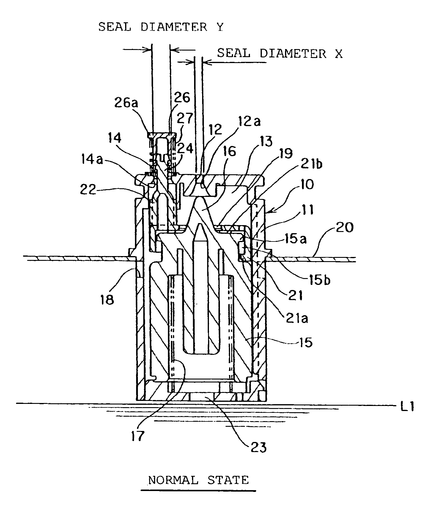
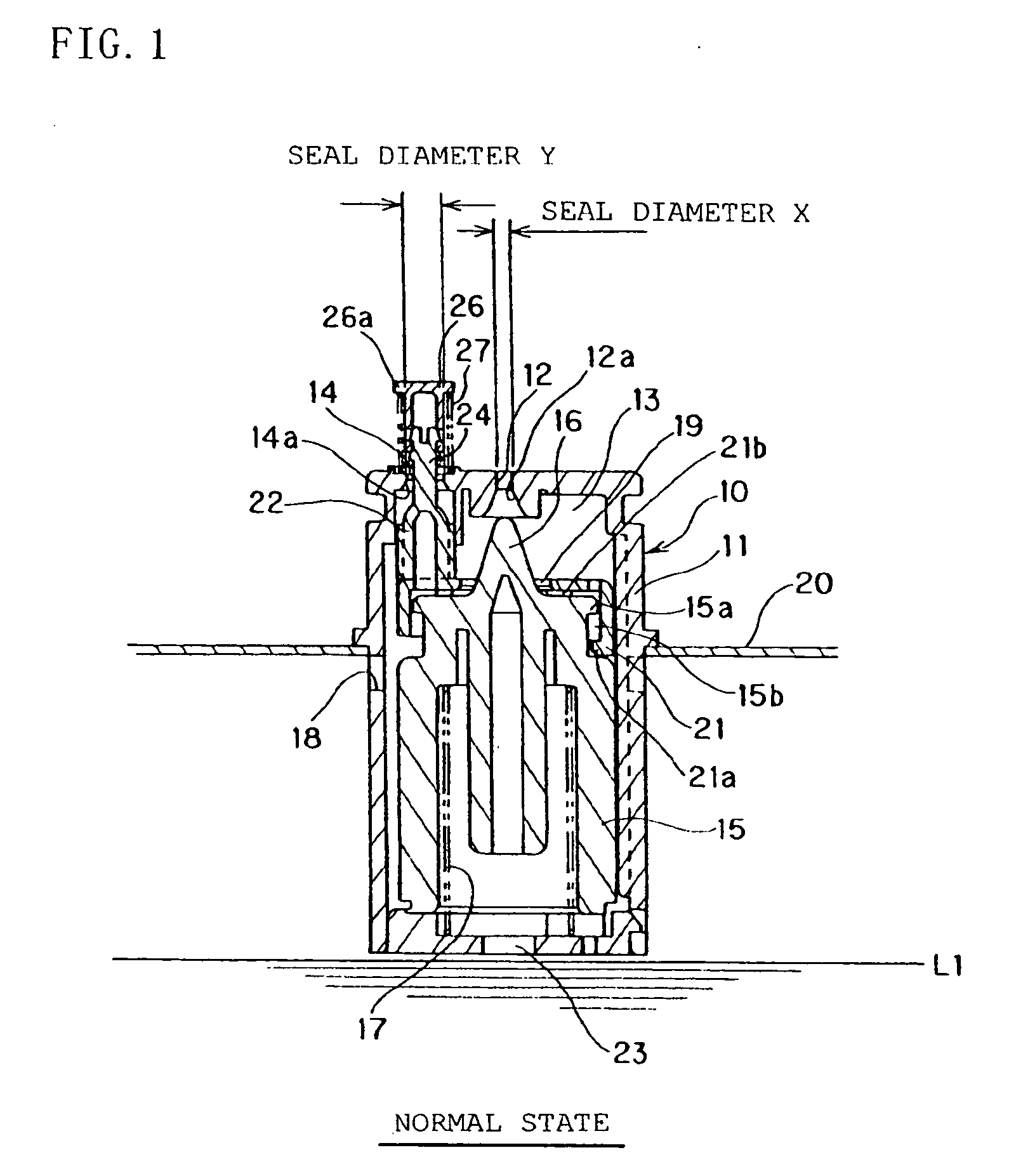
[0023]FIG. 1 is a cross sectional view of a float valve 10 according to the embodiment of the present invention.
[0024]The float valve 10 is attached to the upper part of a fuel tank 20. The upper surface of the float valve 10 is connected with an end of a connecting pipe, which is not shown, for connection with a canister, which is not shown, to guide fuel gas to be generated in the fuel tank to the canister.
[0025]As shown in FIG. 1, the float valve 10 is provided with: a cylindrical case 11 having a space 13 formed inside; a first valve port 12 that is drilled at the center portion on the upper surface of the case 11; a second valve port ...
PUM
 Abstract
Description
Claims
Application Information