Optical pickup apparatus

Inactive Publication Date: 2013-01-17
SHARP KK
View PDF0 Cites 0 Cited by
  • Summary
  • Abstract
  • Description
  • Claims
  • Application Information

AI Technical Summary

Benefits of technology

[0045]The tracking light-receiving region includes a plurality of light-receiving regions for receiving light diffracted in each of the tracking regions selectively in accordance with a type of light that is emitted by the li

Problems solved by technology

This leads to the instab

Method used


Image

  • Optical pickup apparatus
  • Optical pickup apparatus
  • Optical pickup apparatus

Examples


first embodiment

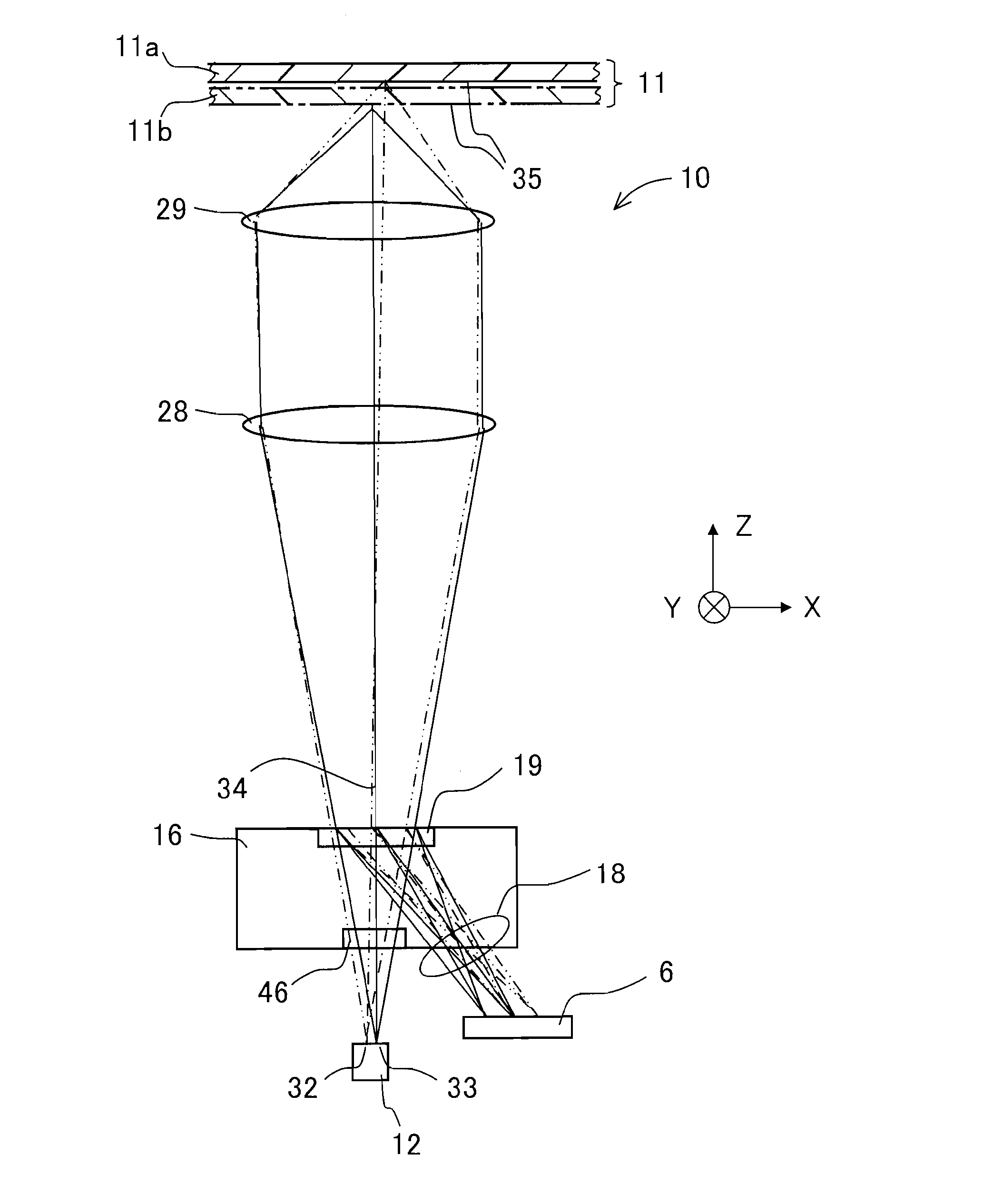
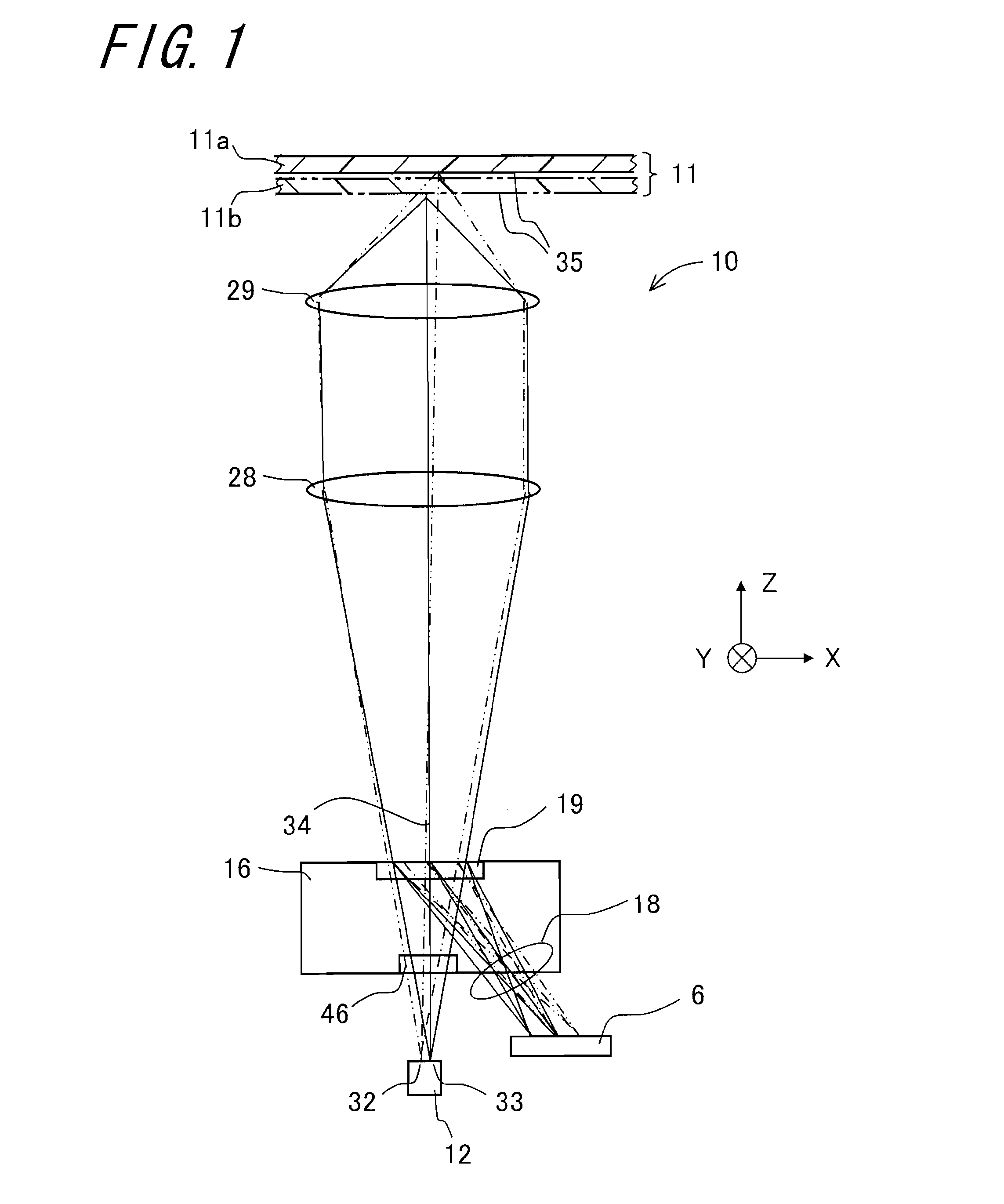
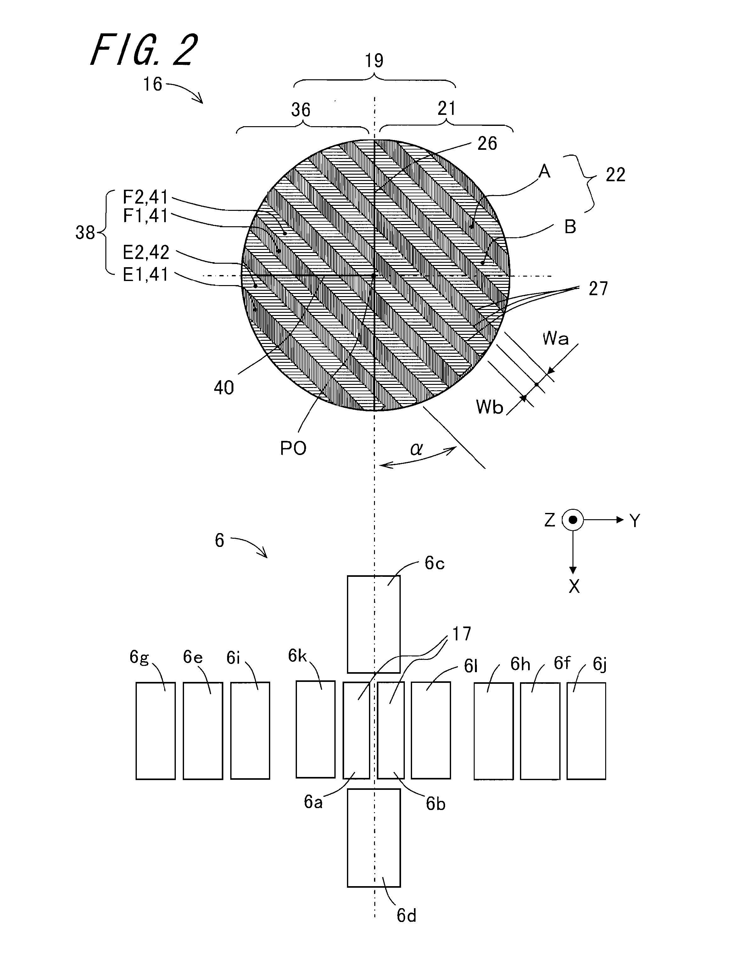
[0063]FIG. 1 is a view showing the structure of an optical pickup apparatus 10 in accordance with a FIG. 2 is a plan view of a diffractive element 16 and a light-receiving element 6. FIG. 3 is a view showing the relationship between the diffractive element 16 and each light-receiving region for the case with light of a first wavelength. FIG. 4 is a view showing the relationship between the diffractive element 16 and each light-receiving region for the case with light of a second wavelength.

[0064]The optical pickup apparatus 10 is an apparatus designed to read information recorded on an optical recording medium 11 by applying light to the optical recording medium 11, causing reflected light 18 from the optical recording medium 11 to undergo positive first-order diffraction in a diffraction region 19, and receiving the resultant diffracted light. In FIGS. 1 and 2, the diffraction region 19 is divided into a plurality of regions by a plurality of dividing lines. The diffraction region...

second embodiment

[0163]FIG. 6 is a view showing the structure of an optical pickup apparatus 210 in accordance with a FIG. 7 is a plan view of a diffractive element 216 and individual light-receiving regions. FIG. 8 is a view showing the relationship between the diffractive element 216 and each light-receiving region for the case with light of the first wavelength. FIG. 9 is a view showing the relationship between the diffractive element 216 and each light-receiving region for the case with light of the second wavelength. FIG. 10 is a view showing the relationship between the diffractive element 216 and each light-receiving region for the case with light of a third wavelength.

[0164]The optical pickup apparatus 210 pertaining to the second embodiment is similar to the optical pickup apparatus 10 pertaining to the first embodiment, and the following description deals mainly with the points of difference of the second embodiment from the first embodiment.

[0165]The optical pickup apparatus 210 pertaini...


PUM


Abstract

An optical pickup apparatus is provided. Segmented regions included in a focus diffraction region includes focus segmented regions corresponding in number with different light emitted by a light source. Different focus segmented regions are arranged adjacent to each other alternately in a direction perpendicular to a parallel dividing line. Segmented regions included in a tracking diffraction region includes tracking segmented regions corresponding in number with different light emitted by the light source. Different tracking segmented regions are arranged adjacent to each other alternately in a direction perpendicular to the parallel dividing line.

Description

CROSS-REFERENCE TO RELATED APPLICATION[0001]This application claims priority to Japanese Patent Application No. 2011-157239, which was filed on Jul. 15, 2011, the contents of which are incorporated herein by reference in its entirety.BACKGROUND OF THE TECHNOLOGY[0002]1. Field of the Technology[0003]The present technology relates to an optical pickup apparatus that emits light to an optical recording medium and receives light reflected from the optical recording medium for performing recording or reproduction of information on the optical recording medium.[0004]2. Description of the Related Art[0005]As a related art, an optical pickup apparatus is described in Japanese Unexamined Patent Publication JP-A 2007-287278. The optical pickup apparatus, being designed to perform recording and reproduction of information on two different types of optical recording media, utilizes light of two different wavelengths, namely light of a first wavelength and light of a second wavelength. An exampl...

Claims


Application Information

Patent Timeline
IPC IPC(8): G11B7/00
CPCG11B7/1353G11B2007/0006G11B7/0906G11B7/0903
Inventor FUKUMOTO, SATORUMURAKAMI, SHINZOH
Owner SHARP KK
Why Eureka
Try Eureka