Terrestrial solar power system using III-V semiconductor solar cells

Inactive Publication Date: 2008-02-07
EMCORE SOLAR POWER
View PDF10 Cites 107 Cited by
  • Summary
  • Abstract
  • Description
  • Claims
  • Application Information

AI Technical Summary

Benefits of technology

[0016]It is an object of the present invention to provide an imp

Problems solved by technology

Although compound semiconductor solar cells have been widely used in satellite applications, in which their power-to-weight efficiencies are more important than cost-per-watt considerations in selecting such devices, such solar cells have not yet been designed and configured for terrest

Method used


Image

  • Terrestrial solar power system using III-V semiconductor solar cells
  • Terrestrial solar power system using III-V semiconductor solar cells
  • Terrestrial solar power system using III-V semiconductor solar cells

Examples


first embodiment

[0047]FIG. 3 is a view of the present invention using a Cassegrain reflector arrangement. In such an arrangement, the solar cell 204 may be mounted in the center of the reflector 301, and a passive heat spreader 302, with cooling fins 303, may be provided.

[0048]In most general terms, the solar cell module is a thin film semiconductor body including a multijunction solar cell having first and second electrical contacts on the back surface thereof. The module includes a support for mounting the solar cell and making electrical contact with the first and second contacts. A heat spreader is attached to the support of the reflector 301 for dissipating heat from the semiconductor body.

second embodiment

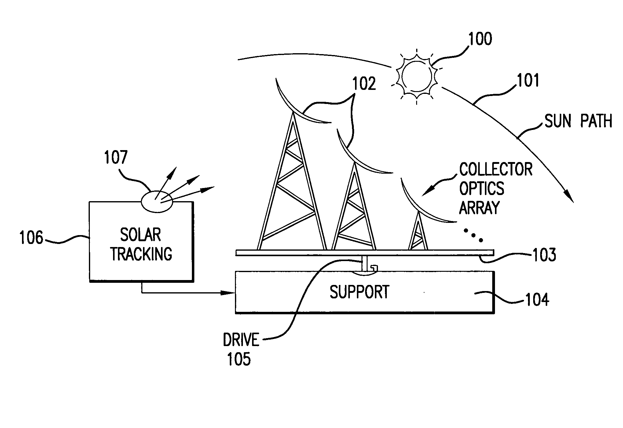
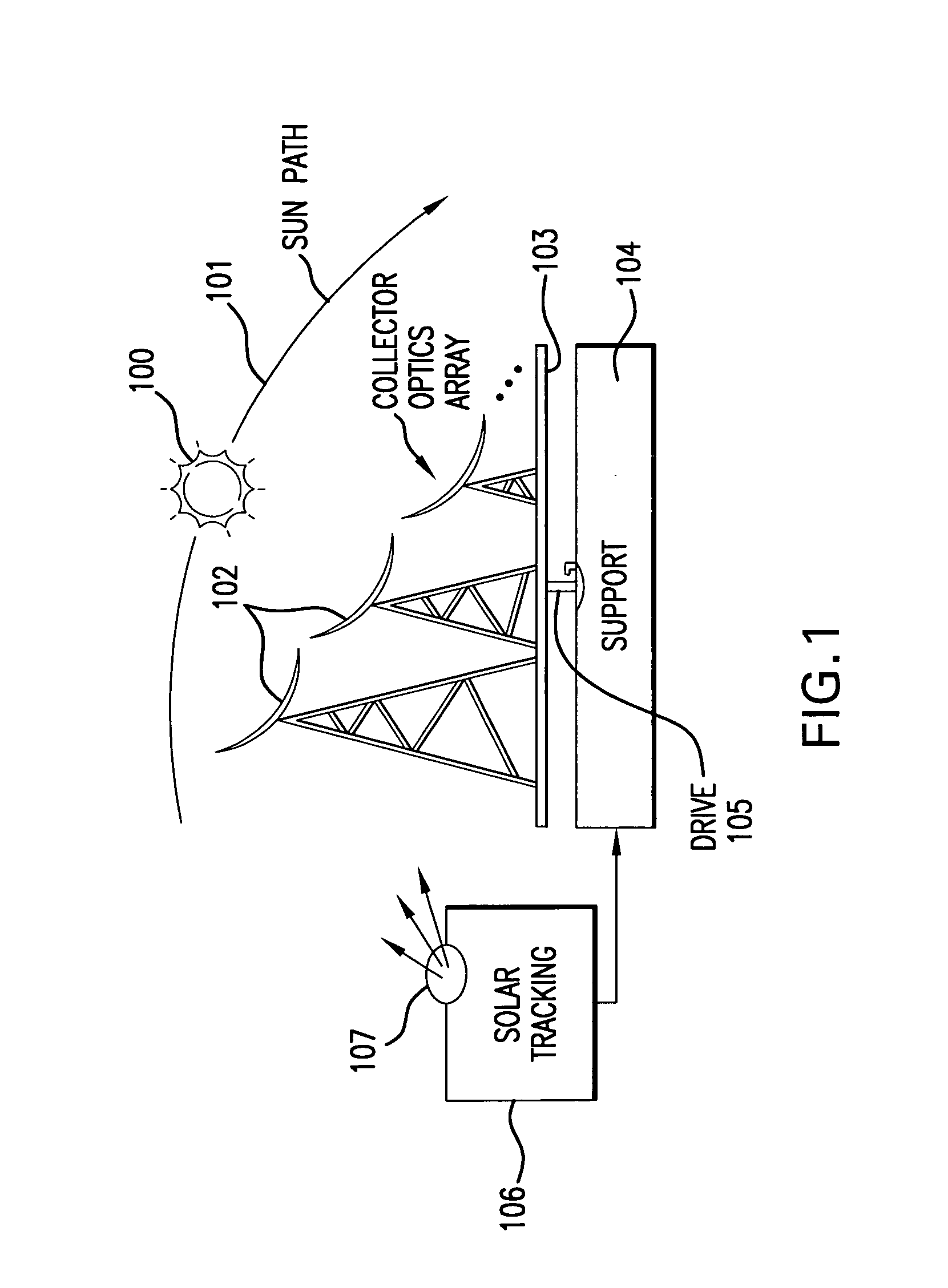
[0049]FIG. 4 is an enlarged view of a parabolic trough solar collector 400 according to the present invention. The trough 401 is one embodiment of the collector optics 102, the trough 401 is positioned to face the sun so that the incoming parallel rays are focused at a focal point along a line, approximately at the center of tube element 402. In one embodiment, the solar cell 406 (such as described in FIG. 2) may be mounted and supported by the tube 402. The tube 402 may be composed of two electrically isolated elements 403 and 404 supported by a dielectric outer support 405. The metallic elements 403 and 404 function as a heat spreader, and may be filled with a circulating liquid to provide even greater cooling to the solar cell 406. The tube 402 is suspended at the focal point by means of a support bracket 408.

[0050]One aspect of the present invention depicted in FIG. 4 is that the solar cell 406 is a flexible thin film and shaped so as to conform to the surface of the tube 402, w...


PUM


Abstract

A system for generating electrical power from solar radiation utilizing a III-V compound multijunction semiconductor solar cell; a concentrator for focusing sunlight on the solar cell, including a concave trough-shaped reflector; and a heat spreader connected to the solar cell for cooling the cell.

Description

REFERENCE TO RELATED APPLICATIONS[0001]This application is related to co-pending U.S. patent application Ser. No. 11 / 109,016 filed Apr. 19, 2005, and Ser. No. 11 / 280,379 filed Nov. 16, 2005.[0002]This application is also related to co-pending U.S. patent application Ser. No. 11 / 45,793 filed Jun. 2, 2006 and assigned to the common assignee.BACKGROUND OF THE INVENTION[0003]1. Field of the Invention.[0004]The present invention relates generally to terrestrial solar power systems for the conversion of sunlight into electrical energy, and, more particularly, to the use of III-V compound semiconductor solar cells in conjunction with reflector concentrators which are connected in an array for unitary movement to track the sun.[0005]2. Description of the Related Art.[0006]Commercially available silicon solar cells for terrestrial solar power application have efficiencies ranging from 8% to 15%. Compound semiconductor solar cells, based on III-V compounds, have 28% efficiency in normal opera...

Claims


Application Information

Patent Timeline
IPC IPC(8): H01L31/042
CPCF24J2/07H01L31/052H01L31/06875H01L31/0725H01L31/0547Y02E10/52Y02E10/544H02S20/00H01L31/0735H01L31/0521F24S20/20
Inventor MCGLYNN, DANIELSHARPS, PAUL R.CORNFELD, ARTHURSTAN, MARK A.
Owner EMCORE SOLAR POWER
Why Eureka
Try Eureka