Vacuum relief unit and method for a pool

Inactive Publication Date: 2008-02-07
CIOCHETTI SR MICHAEL J
View PDF10 Cites 9 Cited by
  • Summary
  • Abstract
  • Description
  • Claims
  • Application Information

AI Technical Summary

Benefits of technology

[0009]According to a second aspect of the invention, the method involves venting chamber air from an otherwise closed air chamber into the pool pumping system when the pressure level in the pool pumping system drops below the first pressure level limit, venting atmospheric air into the air chamber when the pressure level within the air chamber drops below a second pressure level limit that is lower than the first pressure level limit, and delaying operation of the atmospheric air venting device when the pressure within the air chamber is no longer below the second pressure level limit so that atmospheric air continues to be vented into the air chamber by the atmospheric air venting device after the pressure in the air chamber is no longer below the second pressure level limit.
[0010]According to preferred aspects of the invention, the vacuum relief unit ad

Problems solved by technology

Second, the unit is able to absorb transient vacuum spikes (pressure drops), and as a result does not unnecessarily

Method used


Image

  • Vacuum relief unit and method for a pool
  • Vacuum relief unit and method for a pool
  • Vacuum relief unit and method for a pool

Examples


Example

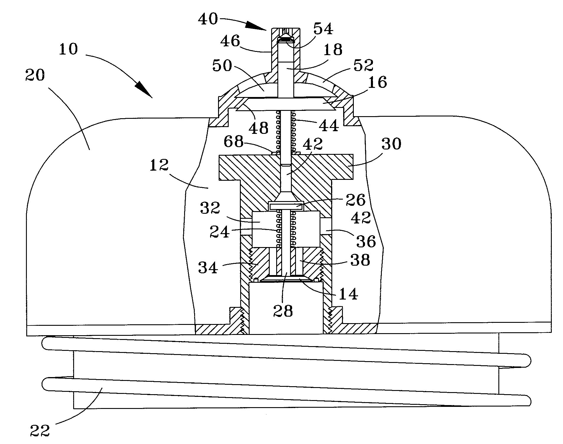
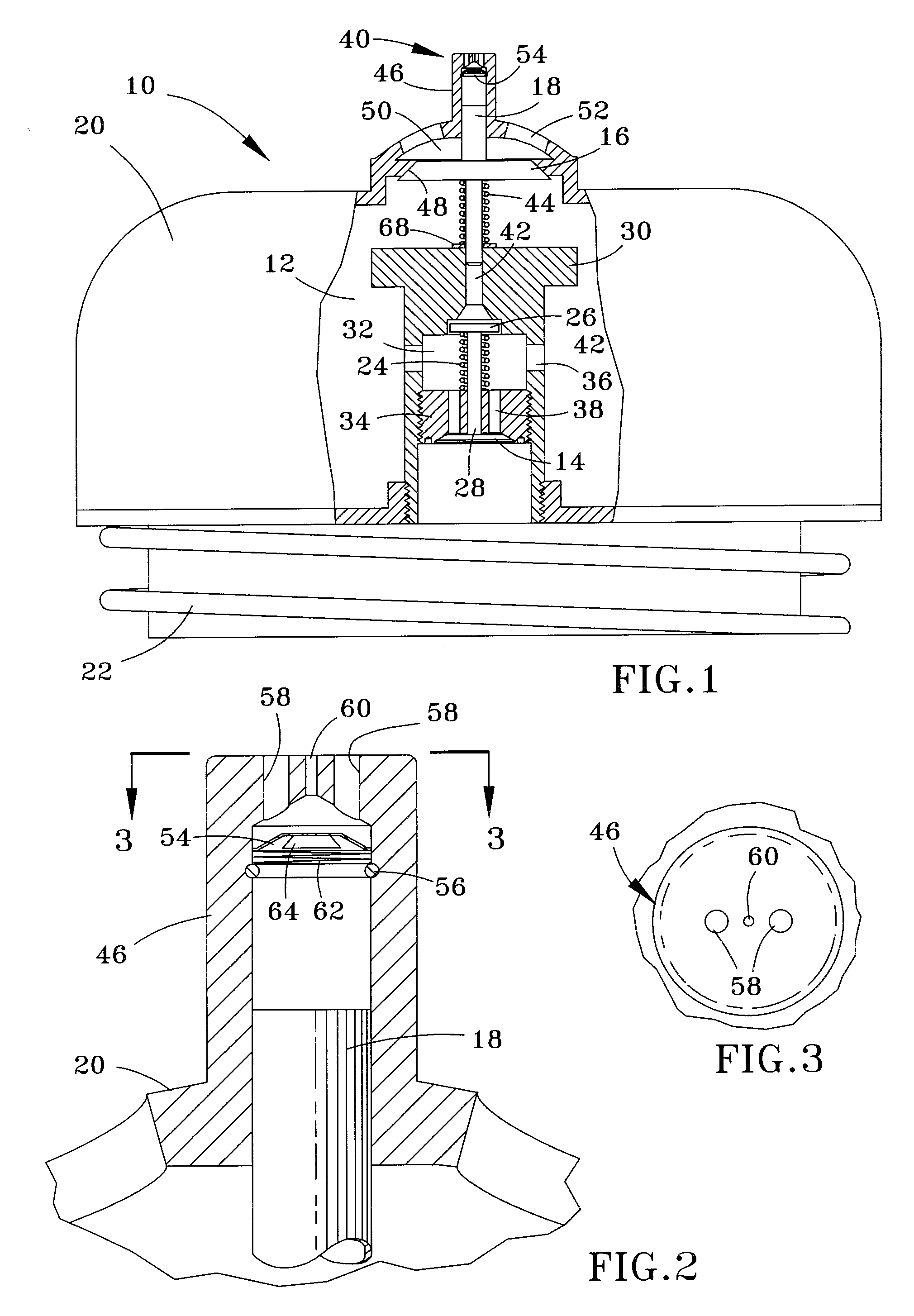
[0016]A vacuum relief unit 10 is represented in the Figures as comprising an air chamber 12 defined by a dome-shaped housing 20, two diaphragms 14 and 16 that operate in series within the housing 20, and a piston 18 also within the housing 20. The housing 20 is configured to be installed in the cover of a pool lint trap (not shown) connected to a pumping system of a pool, hot tub, etc., and is provided with threads 22 at a lower end thereof to permit the housing 20 to be threaded into an opening formed in a conventional lint trap cover. However, it should be understood that the unit 10 is not limited to this type of installation.

[0017]From FIG. 1, it is evident that the first and second diaphragms 14 and 16 are not mechanically coupled to each other. The first diaphragm 14 operates to seal the chamber 12 from a suction line of a pool (not shown) to which the lint trap is connected, and only opens to permit venting of air within the chamber 12 to the suction line if a sufficiently lo...


PUM


Abstract

A vacuum relief unit and method for venting air into a pool pumping system when a pressure level within the system drops below a first pressure level limit. The unit includes a closed air chamber, a device for venting chamber air from the air chamber into the pool pumping system when the pressure level in the pool pumping system drops below the first pressure level limit, a device for venting atmospheric air into the air chamber when the pressure level within the air chamber drops below a second pressure level limit that is lower than the first pressure level limit, and a device for delaying operation of the atmospheric air venting device when the pressure within the air chamber is no longer below the second pressure level limit.

Description

CROSS REFERENCE TO RELATED APPLICATIONS[0001]This application claims the benefit of U.S. Provisional Application No. 60 / 821,466, filed Aug. 4, 2006, the contents of which are incorporated herein by reference. In addition, this application is related to U.S. Pat. Nos. 5,682,624 and 6,251,285, both to Ciochetti and both incorporated herein by reference.BACKGROUND OF THE INVENTION[0002]The present invention generally relates to pool safety equipment. More particularly, this invention relates to a method and unit for preventing an obstruction from being trapped by suction to an inlet of a pool filter pump system. The unit can be mounted directly to a skimmer lid of the pool filter pump system, and operates to vent air into the system when a vacuum level within the system exceeds a specified vacuum limit, as is the case if the drain or another inlet connected to the system is partially or completely obstructed, such as by a child or foreign object.[0003]To maximize enjoyment and maintain...

Claims


Application Information

Patent Timeline
IPC IPC(8): F16K17/02F16K24/04
CPCF16K24/06Y10S137/907Y10T137/3294Y10T137/7838Y10T137/7852Y10T137/7897Y10T137/87917
Inventor CIOCHETTI, MICHAEL J.
Owner CIOCHETTI SR MICHAEL J
Why Eureka
Try Eureka